Categories
Arduino control

Make your prop move

You build this really cool prop. After days, weeks, months of work, it’s done. Just one more thing: it would be so cool if that little bit on top could rotate. But how do you do that? You know motors make things move but you don’t know the first thing about motors. That’s where I come in: I know a fair amount of motors (but I don’t know a whole lot about building great-looking props…).

OK, now what?

To make something move, we need a motor. Here’s a simple one to get started with.

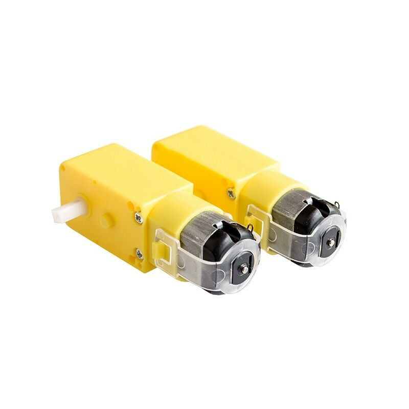
OK, that’s actually two motors. They’re pretty cheap, so why just get one? I’m not going to post links since they’ll be outdated in seconds, but you can generally find these motors for under $5.00 each all over the web. Search “small gearmotor” and you’ll get tons of hits. These are DC gearmotors. “DC” refers to the fact that they run on Direct Current, such as what you get from a battery, as opposed to AC which is what comes from a wall outlet. A gearmotor is a type of motor that contains a gearbox. Normally, motors spin at pretty high speeds: thousands of rotations per minute(RPMs). With the embedded gearbox, we get a more useful rotation rate that’s generally between 15-100 RPM. Slower or faster speeds are available. The ones above has two output shafts that provide around 140 RPM.

OK. I’ll post one link: these guys will probably be selling them for a while

Now, any motor needs a power source. The sample ones above are small enough that they can be battery powered. Three AA’s will run them for quite a while.

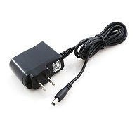
An important feature of DC motors is that their speed depends on the voltage you give them. If you run these from four AA’s they will run faster than if you ran them from two. Normally, they take 4.5 Volts, which is what you would get from the three AA’s mentioned above. If you want them to run all the time, or just don’t want to be bothered replacing batteries, you can also run them from a 5V “wall wart” power supply.

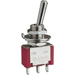
Once we have the motor and a power source, it might be nice to have an easy way to control it. This is where a switch comes in. It completes or breaks the circuit between motor and power and so turns the motor on or off.

So let’s put this all together. You know what this needs? A drawing. Drawings that electrical engineers use to show connections are called schematic diagrams. Here’s what it looks like.

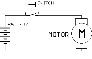
As you can see there are the three elements we talked about: the battery for power supply, a motor, and a switch to turn it on and off. Look at the symbol for a switch: it shows that the contacts (1&2) are not touching. This means that the circuit is incomplete and current will not flow. When the switch is closed by pushing the shiny arm on top, those contacts will touch and complete the circuit, causing current to flow through the motor and making it move.

Enough for now? Next time we’ll wire up actual components and see how that goes.


If you'd like to subscribe to this blog, please click here.

Categories
Uncategorized

PCB Assembly Tips

I recently posted this on Reddit, but after feedback I figured it would be useful here also. Over the years, I’ve accumulated some knowledge about assembling Printed Circuit Boards (PCBs) and it never occurred to me that everyone hasn’t gone through the same school of hard knocks that I have. So here are a few tips when assembling boards.

Here are some of the things I learned over time:

  • Use a stencil if you aren’t already. OSH Stencils makes good quality Mylar stencils at pretty low cost. The time saving versus dispensing solder paste with a syringe is huge.
  • As much as possible, simplify access to the bare components. By this I mean, adjust for how you pick them up. I pick up ICs with a basic vacuum tool, so I keep them in the trays they came in. The resistors/capacitors I pick up with tweezers (my cheapo vacuum pickup doesn’t do so well with small parts), so those are in bulk containers. LEDs are in their tapes, with the polarity clearly marked. The little time-saving details add up.
  • Through-hole components: insert/solder them based on height. Place the lowest-height parts first, otherwise it’s too hard to hold them in place upside down. I use a piece of foam to hold them in place while I solder.
  • It helps to put down extra flux before you place an IC with very close pin spacing like a TQFP part. The flux will help it self-align during reflow and makes solder bridges less likely.
  • If you’re doing multiple boards, it’s faster to place the same part on all boards at once. i.e., making 10 boards: place U1 on all of them, then U2, then R1, R2, then R3, etc. The repetitive motion saves time because muscle memory sets in.
  • Make sure you have assembly costs built into your product before farming out the assembly. I know this sounds obvious, but it’s amazing how many people forget about details like this and end up losing money overall. A good rule of thumb is that your product should sell for 3-5x the Cost of Goods Sold (COGS), which includes assembly cost.


If you'd like to subscribe to this blog, please click here.

Categories
Uncategorized

Start Raspberry pi program on boot

Here is an easy way to start a program for a Raspberry Pi with a Graphical User Interface automatically on boot up.

We’re assuming you are using a recent distro like Raspbian Buster. The autostart folder under ~/.config is where the file goes. The command file format to start your program is:

[Desktop Entry]
Type=Application
Name=HelloWorld
Exec=/usr/bin/python ~/hello.py

Save this file in the autostart folder and call it hello.desktop. This will start a simple “HelloWorld” type program (hello.py) written in Python with a Tkinter GUI framework. It’s probably as simple as it can get.

If you need to run Python under lighttpd, there’s a good tutorial over here.


If you'd like to subscribe to this blog, please click here.

Categories
Uncategorized

Run .NET programs on Raspberry Pi

What was once unthinkable has now happened: you can run software written for Microsoft’s .NET framework on Linux. This means you can now write code in Visual Studio on a PC that can be executed on a pi running Linux.

The process is pretty simple. Let’s start by assuming you have Visual Studio (at least the 2017 version) and a current version of the .NET SDK on your host computer. You can download that from Microsoft here.

Open a new command shell and create a directory called blinky.

Go to the directory: cd blinky.

Type the command dotnet new console

This creates a Visual Studio project called blinky. Replace the Program.cs file with our sample code (TBD) to blink an LED.

Build the program for Linux with the command dotnet publish -r linux-arm

We now have an application package in the publish subdirectory that we can load onto a Raspberry Pi running Linux. Let’s get the pi setup to run .NET Core. We’re going to assume that it’s running Raspbian Debian 9 Jessie since that’s current as this is written.

sudo apt-get install curl libunwind8 gettext apt-transport-https

sudo apt-get update

After the .NET Core framework has been installed, copy the publish directory from your PC to the pi and execute the blinky.exe program to run it. Enjoy your blinking LED!

Here is the source code of the blinky Program.cs

using System;
using System.Threading;
using System.Device.Gpio;

namespace blinky
{
    // Blinks an LED on GPIO pin 16 on a Raspberry pi
    class Program
    {
        static void Main(string[] args)
        {
            Console.WriteLine("Hello World!");
            int pin = 16;
            GpioController controller = new GpioController();
            controller.OpenPin(pin, PinMode.Output);

            int lightTimeInMilliseconds = 1000;
            int dimTimeInMilliseconds = 200;

            while (true)
            {
                Console.WriteLine($"Light for {lightTimeInMilliseconds}ms");
                controller.Write(pin, PinValue.High);
                Thread.Sleep(lightTimeInMilliseconds);
                Console.WriteLine($"Dim for {dimTimeInMilliseconds}ms");
                controller.Write(pin, PinValue.Low);
                Thread.Sleep(dimTimeInMilliseconds);
            }
        }
    }
}


If you'd like to subscribe to this blog, please click here.

Categories
Arduino

Your first Arduino program

So you’ve been hearing about this Arduino thing and you made the jump and downloaded the IDE since it’s a good first step and doesn’t cost anything. Now what?

Well, first of all, what’s an “IDE?” An IDE is an abbreviation for Integrated Development Environment. To write code you need a text editor and to program the Arduino device, you need a programmer. The “I” in Integrated means that the application contains both an editor and a programmer. The Arduino IDE is a very basic one but it gets the job done.

So, what’s a “sketch?” A sketch is the Arduino terminology for a computer program, which is the set of instructions you give a computer to tell it to do something. We also call this “code.” Why the Arduino inventors called a program a sketch I have no idea, but it seems to have stuck.

void setup()
{
}

The lines above are familiar to anyone who’s written an Arduino sketch. The basic outline of a sketch has two of these blocks called “functions.” A function is a short block of code that can be called, or told to execute from anywhere in your program. The other basic function is “loop” and we’ll get to it later. For now, the important thing to know is that setup is called when the program starts and loop is called repeatedly, over and over.

Since setup is called at the beginning, it’s the place where we put statements that need to be executed as soon as the Arduino starts up. e.g., we need to tell it which pins we want to use as inputs and outputs, what special configurations they need, and so on. Here’s a basic program that makes pins 2&3 outputs and blinks them five times.

void setup(void)
{
    // Set pins 2 and 3 as outputs
    pinMode(2, OUTPUT);
    pinMode(3, OUTPUT);

    // Declare a variable for counting
    int i = 0;
    // Turn pins 2 & 3 off 5 times
    // using a for... loop
    for( i = 0; i < 5; i++ )
    {
        // Turn OFF pin 2
        digitalWrite(2, LOW);
        // Turn ON pin 3
        digitalWrite(3, HIGH);
        // Pause for 1000 milliseconds (1 second)
        delay(1000);

        // Turn ON pin 2
        digitalWrite(2, HIGH);
        // Turn OFF pin 3
        digitalWrite(3, LOW);
        // Pause for 1000 milliseconds (1 second)
        delay(1000);
    }
    // Turn OFF pin 2
    digitalWrite(2, LOW);
}

The short block of code above shows something important that’s often ignored: you can do real work in the setup() function. In fact, for some very short programs that just need to do a task and stop, it’s a good way to write your code.


If you'd like to subscribe to this blog, please click here.

Categories
Uncategorized

First Experiments with MPU-6050

OK, so this wasn’t the first experiment but it was the first one I recorded. I’ve wanted to build a stable platform for years, but finally had a reason to do so. The design uses the common MPU-6050 in DMP mode so its internal CPU handles all sensor fusion. I used an excellent MPU6050 library to handle all the interfacing and a small gear motor to move the platform. The whole thing now runs on a basic proportional control and it’s amazingly responsive.Here’s a quick look: https://www.youtube.com/watch?v=Ezwf3kFpk7c


If you'd like to subscribe to this blog, please click here.

Categories
Uncategorized

Quote of the day

Nothing to do with Arduino, but I like remembering this:

“My favorite things in life don’t cost any money. It’s really clear that the most precious resource we all have is time.”

-Steve Jobs


If you'd like to subscribe to this blog, please click here.

Categories
Uncategorized

Arduino peripherals: build or buy?

So you prototyped your grand design using Arduino and some peripherals and shields you bought online. Everything’s debugged and works. Customers are lined up. Now what? Should you continue to wire together Arduinos, external boards, sensors, etc.? Or should you invest in a Printed Circuit Board (PCB) that ties it all together.

It’s not a simple decision. Hopefully this post can help you sort things out.

The “pro’s” of a fully integrated PCB version are

  • You control the size of the device and all its other characteristics like power supply, layout, etc.
  • Fully customized to exactly what you need: no extra parts to pay for.
  • You control the supply: you don’t need to depend on boards that may be unavailable in a year.
  • Quality control is completely up to you. Buy the highest quality parts or the cheapest crap you can find: whatever you need.

But like everything, there are negatives. Here are some of the “con’s”

  • You need to manage inventory yourself, so you’ll have to buy parts whenever you need a new batch of product.
  • The manufacturing is all up to you. Solder the boards yourself or find a Contract Manufacturer.
  • Your costs will likely be higher, because most Arduino peripheral manufacturer have economies of scale on their side (they make more boards) and in Shenzen, their supply chain can provide less expensive parts.
  • You have to deal with components being obsolete or hard to find.

It’s not a simple decision to make on its own. At volumes over 100/year it can start to make sense. Or if you need something in a size and form factor that doesn’t exist off the shelf, then building it yourself is a great alternative. My gut feeling, however, is that for most people, buying off the shelf hardware makes the most sense. Also, if you’re reading this, it’s a fair bet that designing and building electronic hardware isn’t your core competency so it may be bet to leave that up to someone who does it for a living. This gives you the option of having them deal with the problems of manufacturing hardware while you can focus on your application of the hardware.


If you'd like to subscribe to this blog, please click here.

Categories
Uncategorized

arduino Stepper motor control

If you’ve been around the Arduino ecosystem for any length of time, you’ve probably heard about stepper motors. We won’t go into the electromechanics of what makes them tick, but we’ll dive into what they are and some of the things you need to bear in mind when using steppers with your Arduino.

Stepper motors are pretty much designed for our digital age. What sets a stepper motor apart from other DC or AC motors is that they are controlled by sending them electrical pulses. Each pulse causes the motor to move a discrete distance known as a step. The motors in common usage typically move 200 steps per revolution. That works out to 1.8 degrees per step. Now, the step size can be changed depending on how the motor pulses are arranged, so it’s common to run these motors in half steps to achieve 0.9 degrees per step.

Stepper motors excel at positioning. Since they can be moved a fixed number of steps without any additional hardware, they make great positioners as long as you stay within the motor’s limits. Where the positioning can fail is when an external load that’s more than the stepper can hold is applied. Motors are rated by their holding or running torque, which is the amount of force at a certain distance from the center of the shaft. Holding torque is the torque that the motor provides at rest. It’s usually much higher than running torque, which is the torque provided as the motor is moving. Running torque typically drops off at higher speeds.

As your program sends steps to the motor, it’s normal to keep track of the number of steps, since that tells you exactly where the motor has moved to. If you apply force that exceeds the motor’s torque, then the shaft will move and the motors position will become unknown. So your software may believe that the motor is at position 1547 and perhaps this means it moved 203mm, but since the load was forcibly moved (perhaps it jammed), the real position may only be 194mm.

Homing

Since the motor’s position can be changed by external forces, it stands to reason that at startup, we don’t know what position it’s in at startup. To figure that out, we need to move to a known, or Home, position. It’s typical to have a sensor at the home position and a “flag” is attached either to the motor shaft or to the axis that drives the load. The home position is usually at the extreme end of motion. This means that although the motor may not know where it is, it will always know that direction Home is in. To home the system, we slowly move the motor in the home direction until the home sensor is activated by the flag. Home is normally the zero position, so we reset our axis position to zero at this point.

Common drive settings

Many manufacturers provide stepper motor drives to the Arduino community. The more sophisticated ones allow you to set the step size (full, half, etc). Some offer current feedback to run the motor at a fixed current. Limit switch inputs are another common feature.

Running faster

Most Arduino motor tutorials tell you to run the motor at the voltage on its end plate. This is fine: it will make sure that the motor will never overheat, but it’s not the way to get the most performance out of the motor.

The primary limit on a stepper motor isn’t the voltage it’s run at, it’s the current allowed. You also need to consider temperature. Most medium size steppers are rated to run up to about 150 degrees F.

The stepper motor speed is directly proportional to the rate at which it receives the step pulses. Now, at a certain point, you’ll notice that the motor isn’t moving faster as your step rate increases. In a nutshell, this is because the voltage can’t get high enough to keep driving the motor faster. We can easily rectify this by increasing the voltage. Now, if we increase the voltage, we will increase the power that the motor dissipates and that increased power makes it hotter. Remember, we don’t want it to get too hot.

There are two main ways around this problem of wanting to apply a high voltage, but keep the power low. As we mentioned above, some motor drives have a feedback setting so they limit the current to the motor, alternately you can place a high power resistor in line with the motor power input and that will limit the current. The higher voltage applied will allow the motor to respond at higher step rates and provide greater running torque.

Microstepping

You may have heard of microstepping, where you can move a stepper a small fraction of a step. Quarter, eighth, or sixteenth or even finer steps are possible. However, it’s important to note that reducing the step size is typically done to achieve a smoother motion. The motor is not usually designed to be accurate at such small step sizes, so an eighth of a step will not necessarily move a consistent distance.


If you'd like to subscribe to this blog, please click here.

Categories
Uncategorized

Counting Reflective objects

Retroreflective sensors are pretty convenient. They consist of an LED emitter that sends a (usually infrared) beam of light and a light sensor integrated in the same package. The LED is aimed at a reflector (hence the retroreflective name) and the reflector bounces the light beam back to the sensor. Do this on a conveyor belt, and every time an object on the belt blocks the beam, it causes a signal change that can be counted. This is more convenient than a through-beam sensor that requires the LED emitter on one side and the sensor on the other. That additional cabling can be a hassle. Using the reflector means that cabling is only needed on one side and that simplifies installation.

One problem with retroreflective sensors is when you need to detect a shiny object. Say you have a production line that packages product in reflective Mylar bags. The count sensor may not be able to distinguish between a reflection from the retroreflector or the bag. This means that a reflection caused by the bag gives exactly the opposite state than you want. The bag is obviously present, but it being reflective means the sensor “thinks” there is nothing in front of it.

A possible solution is to use polarized light. By polarizing the light and using a corner-cube reflector, only changes caused by the light being blocked will be detected, so the shiny Mylar packaging is no longer an issue.

Another approach is to debounce the signal. The bag moving past the sensor causes multiple fast transitions (the problem with counting reflective objects is often that a single object causes too many counts). Debouncing is a technique where the fast, multiple transitions are ignored in favor of a slower change. We have used this technique to assist a customer who needed to count shiny objects moving on a conveyor belt and it made a great improvement in the situation.


If you'd like to subscribe to this blog, please click here.