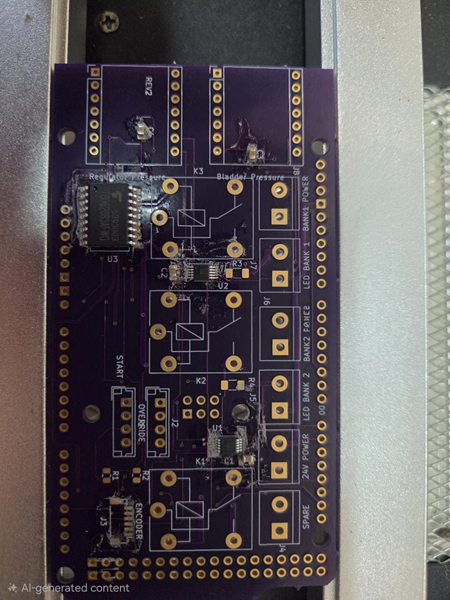
I was having a bunch of trouble soldering drivers with heatsink pads on the underside. The combination of inaccessible pads and a large heatsinking area of copper combined to make it difficult to reflow the solder paste. About a year or so ago I picked up a cheap board preheater but didn’t do much with it. I was mainly hoping it would work as a small IR reflow plate, but it doesn’t quite generate enough heat for that.
However, it works really well for its intended purpose. Preheating the board and components before hot-air reflow allows the solder paste under large components to come up to temperature and results in a beautifully soldered part.
Thumbs up on these cheap little preheater plates.
If you’d like to subscribe to this blog, please click here.
One of my uses for this blog to is to record useful information that I (and others) might need later. This is about an annoying problem I ran into.
I’ve used the DfRobot Player Pro a couple of times in “stand alone” mode. It’s a great audio player: small, cheap, and easy to use. It also has a serial interface so it can be controlled by an arduino or microcontroller. DF Robot provides the DFRobot_DS1201S library to make this easier. However, all the examples I see online are using the playFileNum(num) command that takes an index of a file (MP3) to be played. The problem with this is that the file index depends on the order in which the file file was stored to the Player Pro’s Flash memory.
There is also a playSpecFile(String) method that takes a filename, which you’d expect is much easier and would be more popular. However, when I tried using it, it always played the same song. OK, time to debug. There is also a method in their library to retrieve the name of the currently playing file. However, when I use code like this:
// Play file
DF1201S.playSpecFile("one.mp3");
// Print name of file that's playing
Serial.println(DF1201S.getFileName());
DF1201S.playSpecFile("two.mp3");
// Print name of file that's playing
Serial.println(DF1201S.getFileName());
DF1201S.playSpecFile("three.mp3");
// Print name of file that's playing
Serial.println(DF1201S.getFileName());
It always plays the same song and to boot, I get Chinese characters displayed for the file name. Clearly, not what I was trying to play.
However, make a minor change to the filename and this works.
// Play file
DF1201S.playSpecFile("/one.mp3");
// Print name of file that's playing
Serial.println(DF1201S.getFileName());
DF1201S.playSpecFile("/two.mp3");
// Print name of file that's playing
Serial.println(DF1201S.getFileName());
DF1201S.playSpecFile("/three.mp3");
// Print name of file that's playing
Serial.println(DF1201S.getFileName());
This plays three different songs correctly and their filenames are reported accurately.
HTH everyone who’s run into the same problem 🙂
If you’d like to subscribe to this blog, please click here.
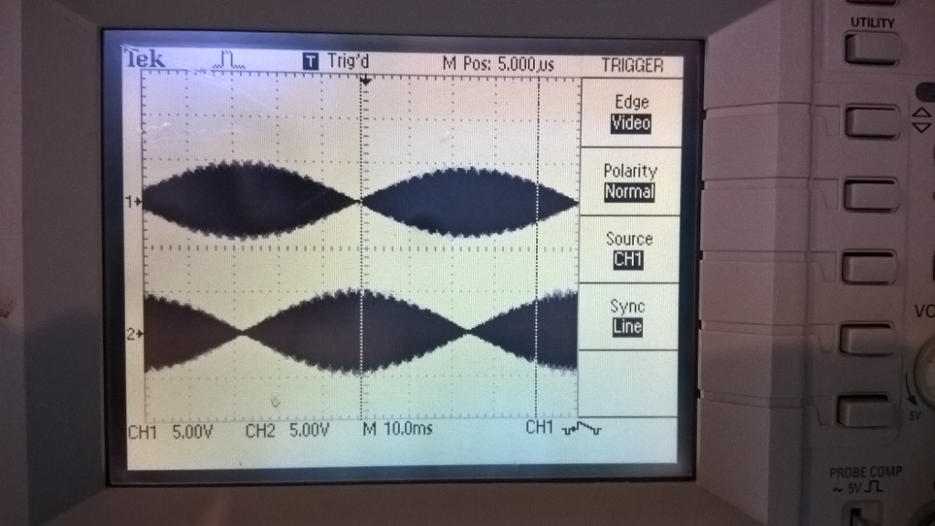
Yes, you read that right. You can go digital-to-resolver in addition to the more common resolver-to-digital. The converter also takes 0-10V signals and can output a corresponding resolver sine-cosine phased signal.
If you’d like to subscribe to this blog, please click here.
I have one of these Mitutoyo Digimatic indicators and thought it would be fun to get a larger display and to be able to record data.
For those who aren’t familiar, Mitutoyo is an instrumentation company that builds amazing measuring instruments. The image above is a digital dial indicator that measures to a precision of 0.0001″ and can be switched between inch or millimeter units. It uses a vacuum fluorescent display, so it’s readily visible, but kind of a power hog.
Digimatic is a product line dating back to at least the 80’s that provides measurement data digitally from the device. It’s a pretty simple protocol and easily decodable with Arduino.
If you’d like to subscribe to this blog, please click here.
Software and hardware integration is a general term for accessing external hardware devices from your PC, tablet or phone. Most existing systems handle common devices such as a printer, as part of the normal operations. But what about a weigh scale? Or a temperature sensor? Or a counter? What if you need to track when an item enters a manufacturing cell and again when it leaves? There are examples of sensor data that your desktop PC or server is not equipped to handle without additional software drivers or specialty applications.
Communication channels
Ethernet, USB, Wi-Fi and Bluetooth are all modern methods of communicating with external devices. There are older communication channels such as RS232 serial that is not well supported by modern PCs. Newer scales often use USB or Ethernet these days.
Wi-Fi and Bluetooth have become very popular for sensor communications because they remove the need for a physical cable connecting the sensor and computer.
While RS232 is a very old protocol (it dates back to the late 1960’s!) that is not directly supported by hardware in modern PCs, it has been so popular over the years that alternate ways of connecting to RS232 ports have arisen. Typically, if you have a PC and need to connect to something with an RS232 serial port, such as a scale, you can use a USB to Serial adapter to handle this task.
Hardware/software integration, also known as system integration, involves combining hardware components and software applications into a cohesive system. This process ensures that different hardware and software elements work together seamlessly, allowing for efficient data sharing and process automation.
Key Components of Hardware/Software Integration:
Hardware: Physical devices such as sensors, cameras, or measuring instruments.
Sensors: Convert analog signals from hardware into digital data.
Connectors: Communication buses like USB, Wi-Fi, Bluetooth, or Ethernet that transfer data between hardware and computers.
Software: Programs that control hardware tasks and process data.
Benefits of Integration:
Improved Efficiency: Streamlines workflows by enabling different systems to communicate and share data.
Cost Savings: Often cheaper than replacing disjointed systems with a new one.
Enhanced Decision-Making: Provides accurate and comprehensive data for better analytics and reporting.
Challenges:
Compatibility Issues: Different systems may use various technologies, requiring significant effort to integrate.
Security and Compliance: Ensuring data security and compliance with regulations can be complex.
Examples:
Temperature Monitoring: Systems that record and report temperature data from thermometers.
Food Wastage Monitoring: Applications that track food wastage using weighing scales and cameras.
If you’d like to subscribe to this blog, please click here.
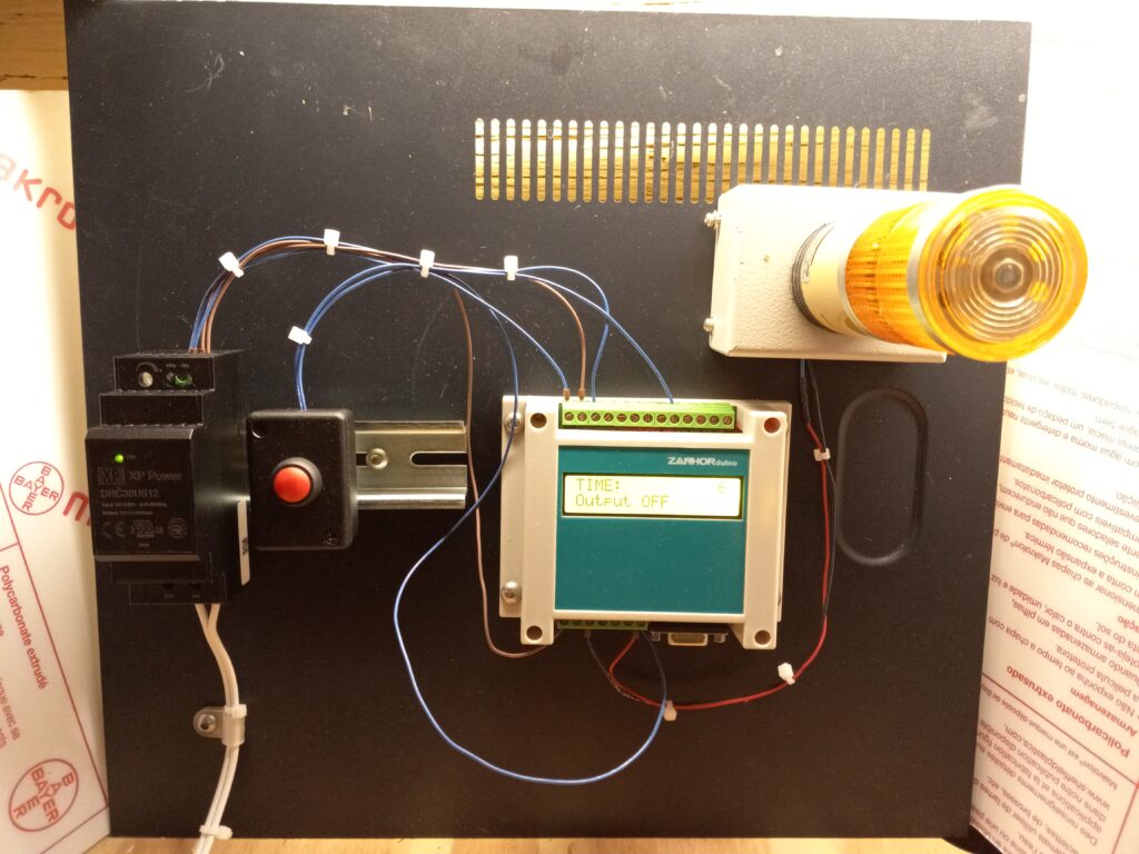
Time is probably the most commonly controlled process variable. Timers are all over the place in industrial control. Odds are, if you need some type of timer, no matter how strange, you can find it off the shelf.
Now, many of these timers used a chip usually referred to as the “555.” The LM555 originally made by (I think; someone will correct me) National Semiconductor was a very versatile device, but it was at the heart of many time-delay relays, short timing circuits, etc.
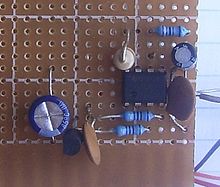
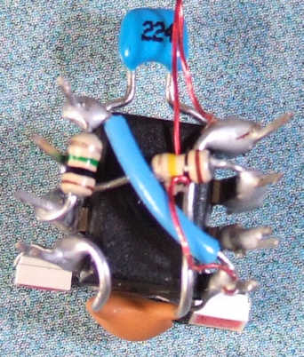
So once upon a time, if you wanted to build a basic timer, odds are you would wire up a 555 into a circuit. To build a handful, or just one, you’d use a perf board,
maybe you might use wire wrap or even dead-bug construction (my favorite!)
It would be time consuming,but maybe you had no choice because the timer had some weird requirement that no off the shelf timer had, or needed to fit into an oddly shaped space.
What does this have to do with Arduinos? Well, you can program any timing sequence into an Arduino. Say you want the heater on a commercial ironing board to come on for five seconds when the operator lowers it, a 555 does it easily. If you want the heater to come on for five seconds and when the board is raised again, a fan to blow for 10 seconds to cool the clothing, the 555 can still be used. Maybe you need two of them. But now, the Arduino becomes an easier solution. Whether you need one time sequence, or dozens, a single Arduino can be programmed to do it. When you factor in the labor of wiring a circuit board with the 555, the low off the shelf price of the Arduino makes it even more attractive.
This is the wonder of the time we live in: an off the shelf microprocessor board is now inexpensive enough to be used for logic replacement.
Amazing
If you’d like to subscribe to this blog, please click here.
Resistors are one of the fundamental electronic components. They fall into the category of linear devices because their behavior is predictable by a linear equation. That is, the voltage across a resistor is a linear multiple of the current passing through it:
voltage (V) = Current (i) x Resistance (R)
Important resistor characteristics
The resistance, the amount that a resistor impedes or “resists” current flow, is measured in ohms. Commonly, the Greek letter omega Ω is used as an abbreviation. e.g., a 10,000 ohm resistor is shown as 10kΩ. The power rating of a resistor is measured in Watts (W). In many applications, the power rating is important because if it is exceeded, the resistor will become very hot and physically fail, possibly even bursting into flames. For most applications in Arduino-based circuits, power is not likely to be a significant issue.
What they look like
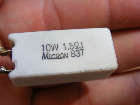
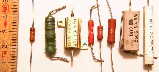
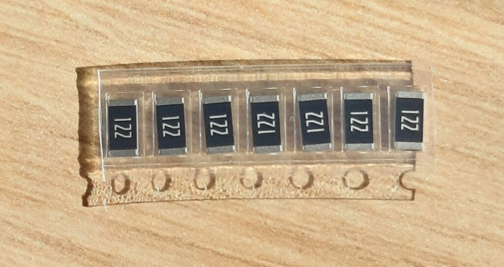
Resistors can take a lot of different physical shapes. Here are a few examples.
1.5ohm, 10Watt Power resistor
(By Emilian Robert Vicol from Com. Balanesti, Romania – Ceramic-Encapsulated-Resistor_23268-480×360, CC BY 2.0, https://commons.wikimedia.org/w/index.php?curid=38383544)
Various through-hole resistors
Surface-mount resistors
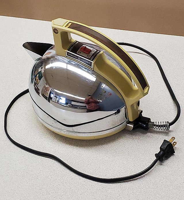
Electric kettle
Yes, an electric kettle is an example of a very high-power resistor. It uses the resistance of high-temperature wire to turn the electricity into heat.
What do we need them for?
The function of a resistor is to impede current flow. That’s it. That’s literally all they do. However, that simple statement means that they can be used for lots of different things.
Pullups/pulldowns the digital inputs to a microcontroller need to have a set HIGH or LOW state. This means that they must be fixed to the positive voltage supply (Vcc) or ground (GND). Leaving them to find their own voltage level can cause the state of the input to be constantly changing between HIGH and LOW as that floating voltage changes. A pullup or pulldown resistor is normally used if the device that is driving the input does not have a natural HIGH or LOW state. We would not want to connect the input directly to Vcc or ground, because in that case, if we were to connect the input to a signal that changes the inputs’s state, it would mean a short circuit between Vcc and ground, which is a serious problem.
One example of such a device would be a switch. Most modern processors include an internal circuit that allows the programmer to enable the input to be pulled up to Vcc, but still allows a switch or other device to drive the input to a LOW state. This is called an “internal pull up.” In many cases, an internal pull down can also be configured.
If the processor does not have built-in pull ups, or if a stronger pull up is needed (the internal ones are quite weak: on the equivalent of a 100k resistor), then an external resistor can be used in this case.
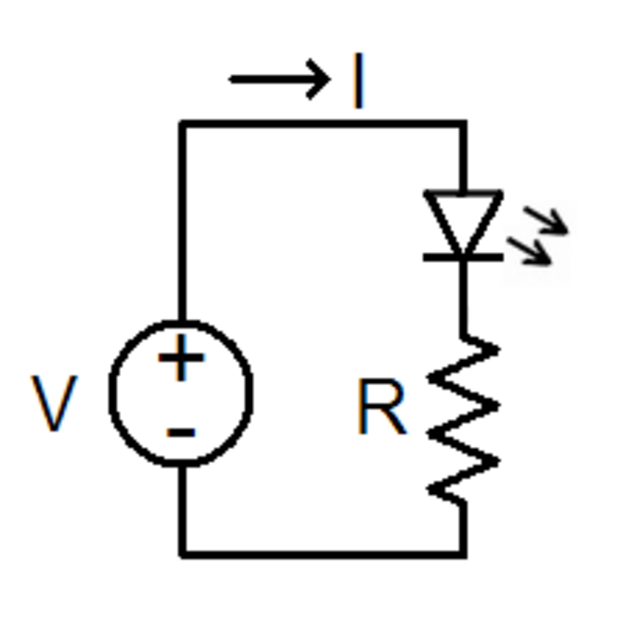
Current limiting This circuit uses a resistor to limit the current through a Light Emitting Diode (LED). Without the resistor, the LED would consume too much current and likely fail from overheating.
LED current limiter
A pair of resistors can reduce a voltage. In the diagram below, there are two resistors, R1 and R2. The zigzag is the standard schematic diagram symbol used to depict a resistor. Here an input voltage, Vin, is changed by the formula below to an output Vout. This circuit configuration is called a voltage divider because it divides the input voltage by a fixed amount.
If you’d like to subscribe to this blog, please click here.