Time is probably the most commonly controlled process variable. Timers are all over the place in industrial control. Odds are, if you need some type of timer, no matter how strange, you can find it off the shelf.
Now, many of these timers used a chip usually referred to as the “555.” The LM555 originally made by (I think; someone will correct me) National Semiconductor was a very versatile device, but it was at the heart of many time-delay relays, short timing circuits, etc.
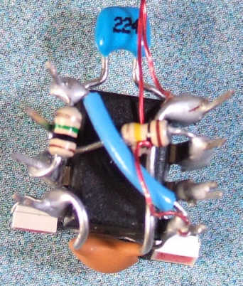
So once upon a time, if you wanted to build a basic timer, odds are you would wire up a 555 into a circuit. To build a handful, or just one, you’d use a perf board,
maybe you might use wire wrap or even dead-bug construction (my favorite!)
It would be time consuming,but maybe you had no choice because the timer had some weird requirement that no off the shelf timer had, or needed to fit into an oddly shaped space.
What does this have to do with Arduinos? Well, you can program any timing sequence into an Arduino. Say you want the heater on a commercial ironing board to come on for five seconds when the operator lowers it, a 555 does it easily. If you want the heater to come on for five seconds and when the board is raised again, a fan to blow for 10 seconds to cool the clothing, the 555 can still be used. Maybe you need two of them. But now, the Arduino becomes an easier solution. Whether you need one time sequence, or dozens, a single Arduino can be programmed to do it. When you factor in the labor of wiring a circuit board with the 555, the low off the shelf price of the Arduino makes it even more attractive.
This is the wonder of the time we live in: an off the shelf microprocessor board is now inexpensive enough to be used for logic replacement.
Amazing
If you’d like to subscribe to this blog, please click here.
Arduinos are popular small microcontroller boards that have many applications. However, they’re not designed to switch loads above a few milliamps: say a couple LEDs or so. While power-driver shields do provide this capability, they also can consume more resources than you may be able to give up.
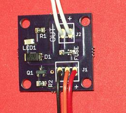
We developed a high current driver to make it easy to control a solenoid valves with Arduino. It will also control pumps and motors. With an adapter cable, it can easily connect to your Arduino, BeagleBone, Raspberry Pi or other digital controller without soldering or crimping any connections. Doesn’t get any easier than that.
The power driver board was born out of a need for controlling a 1 amp solenoid valve using an Arduino. The solenoid valve was being used to control the water flow to fill a tank automatically. Now there’s a simple way to use your Arduino or compatible to switch up to 3A at 24VDC. Two output connections (the white wires shown above) connect directly the load (your solenoid, relay, motor, etc) and the power (red, black) go to the power supply (5 -24 volts). The orange lead is used to switch on and off. This is a low-voltage (5V) control that can connect directly to a microcontroller, or development board. An onboard LED indicates when the load is switched on.
Here’s some sample code that implements a timer with an Arduino. When the pushbutton is pressed, it turns on water flow for 3 seconds
// This sketch demonstrates a simple timer
// A load (motor, solenoid, relay, solenoid valve is on Pin 1
// A pushbutton to trigger the timer start is on pin 2
//
// When the pushbutton is held down for more than 0.1 second
// then released, the timer starts
// and times out after 3 seconds
//
// Timer is retriggerable: if pushbutton pressed
// during the timeout period, timer restarts
//
// Constant definitions
#define LOOP_INTERVAL 10
#define TIMEOUT 300 * LOOP_INTERVAL
#define TRIGGER_INTERVALS 10
#define TIMER_INACTIVE -1
#define TRIGGER_PIN 0
#define OUTPUT_PIN 1

void setup()
{
  pinMode(OUTPUT_PIN, OUTPUT);
  pinMode(TRIGGER_PIN, INPUT_PULLUP);
}

void loop()
{
  static int count = 0;
  static int timer = TIMER_INACTIVE;
  // Process loop periodically
  delay(LOOP_INTERVAL);

  // Check trigger input
  if (digitalRead(TRIGGER_PIN) == LOW)
  {
    // Must hold down pushbutton for the entire interval and
    // then release to trigger
    count++;
  }
  else
  {
    // push button released. Check if we should start timing
    if (count >= TRIGGER_INTERVALS)
    {
      // Turn output ON (timeout is retriggerable)
      digitalWrite(OUTPUT_PIN, HIGH);
      timer = TIMEOUT;
    }
    count = 0;
  }

  // If timer active, count down
  if (timer != TIMER_INACTIVE)
  {
    timer -= LOOP_INTERVAL;
    if (timer == 0)
    {
      // Turn output OFF
      digitalWrite(OUTPUT_PIN, LOW);
      timer = TIMER_INACTIVE;
    }
  }
}
Let’s find out what new applications you can come up with.
If you’d like to subscribe to this blog, please click here.
Unless you’ve been hiding under a particularly large rock, you must have hear of OpenAI’s chatGPT: a publicly accessible Artificial Intelligence that is surprisingly helpful. How helpful? Well, it can even be used to write Arduino code!
And that’s where the problems begin. For an experienced programmer, chatGPT is amazingly useful: it can produce custom versions of commonly-needed code in seconds. However, for a beginner, or a non-programmer, the downsides may outweigh the benefits. One of the problems with chatGPT-generated Arduino code is that it can be wrong in subtle, or even obvious ways. To someone who writes code for a living (like yours truly), these bugs are easy to find. For a neophyte, it looks fine and it’s not until they try to run it that it fails in mysterious ways. And worst of all, as good as chatGPT is at writing code, it’s terrible at debugging it. So if your Arduino code that chatGPT generated doesn’t work, you’re pretty much out of luck.
I’ve been getting more and more email from people in this particular quandary. They’ve tried using chatGPT to write code for their desperately-needed Arduino system, but it doesn’t work and they can’t figure out why.
Well, that’s why this site is here: we can fix the problem and write professional grade code that you can rely on, and best of all, it works 🙂
If you’d like to subscribe to this blog, please click here.
Resistors are one of the fundamental electronic components. They fall into the category of linear devices because their behavior is predictable by a linear equation. That is, the voltage across a resistor is a linear multiple of the current passing through it:
voltage (V) = Current (i) x Resistance (R)
Important resistor characteristics
The resistance, the amount that a resistor impedes or “resists” current flow, is measured in ohms. Commonly, the Greek letter omega Ω is used as an abbreviation. e.g., a 10,000 ohm resistor is shown as 10kΩ. The power rating of a resistor is measured in Watts (W). In many applications, the power rating is important because if it is exceeded, the resistor will become very hot and physically fail, possibly even bursting into flames. For most applications in Arduino-based circuits, power is not likely to be a significant issue.
What they look like
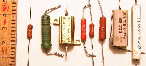
Resistors can take a lot of different physical shapes. Here are a few examples.
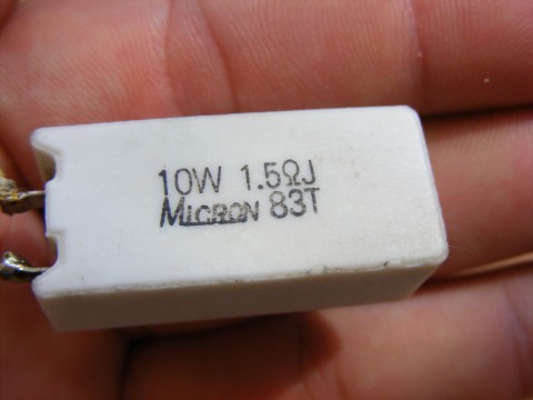
1.5ohm, 10Watt Power resistor
(By Emilian Robert Vicol from Com. Balanesti, Romania – Ceramic-Encapsulated-Resistor_23268-480×360, CC BY 2.0, https://commons.wikimedia.org/w/index.php?curid=38383544)
Various through-hole resistors
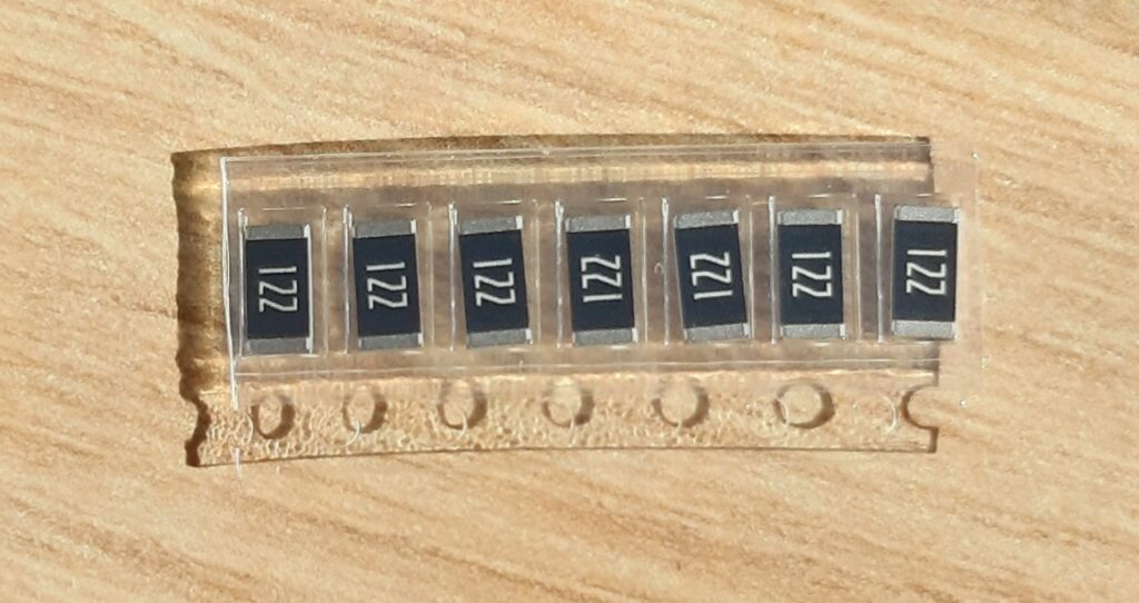
Surface-mount resistors
Electric kettle
Yes, an electric kettle is an example of a very high-power resistor. It uses the resistance of high-temperature wire to turn the electricity into heat.
What do we need them for?
The function of a resistor is to impede current flow. That’s it. That’s literally all they do. However, that simple statement means that they can be used for lots of different things.
Pullups/pulldowns the digital inputs to a microcontroller need to have a set HIGH or LOW state. This means that they must be fixed to the positive voltage supply (Vcc) or ground (GND). Leaving them to find their own voltage level can cause the state of the input to be constantly changing between HIGH and LOW as that floating voltage changes. A pullup or pulldown resistor is normally used if the device that is driving the input does not have a natural HIGH or LOW state. We would not want to connect the input directly to Vcc or ground, because in that case, if we were to connect the input to a signal that changes the inputs’s state, it would mean a short circuit between Vcc and ground, which is a serious problem.
One example of such a device would be a switch. Most modern processors include an internal circuit that allows the programmer to enable the input to be pulled up to Vcc, but still allows a switch or other device to drive the input to a LOW state. This is called an “internal pull up.” In many cases, an internal pull down can also be configured.
If the processor does not have built-in pull ups, or if a stronger pull up is needed (the internal ones are quite weak: on the equivalent of a 100k resistor), then an external resistor can be used in this case.
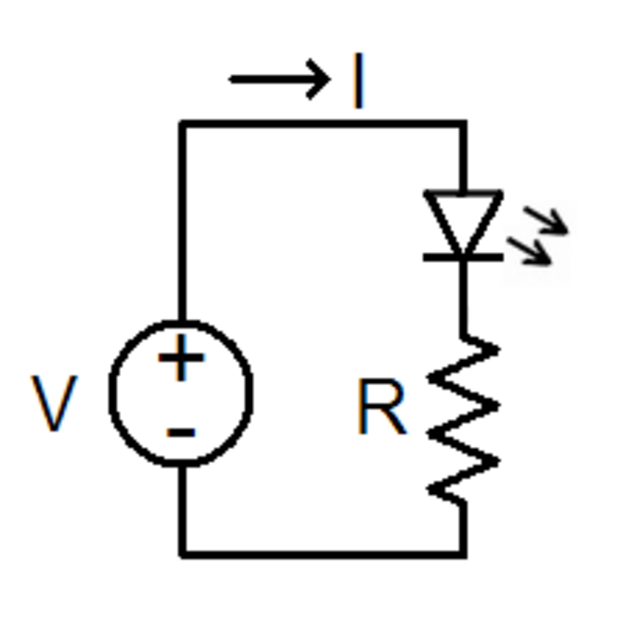
Current limiting This circuit uses a resistor to limit the current through a Light Emitting Diode (LED). Without the resistor, the LED would consume too much current and likely fail from overheating.
LED current limiter
A pair of resistors can reduce a voltage. In the diagram below, there are two resistors, R1 and R2. The zigzag is the standard schematic diagram symbol used to depict a resistor. Here an input voltage, Vin, is changed by the formula below to an output Vout. This circuit configuration is called a voltage divider because it divides the input voltage by a fixed amount.
If you’d like to subscribe to this blog, please click here.
I recently had to make a field upgrade to the software on some ESP32-based devices. I didn’t want to have to require that the operator go through the entire process of installing the Arduino IDE, download libraries, and all that not-so-fun stuff. For us techies, it’s no big deal. For a non-technical user who has tons of more important things to do, it becomes a royal pain in the butt.
So, what to do? From watching the IDE output, I could see that it called esptool.exe. A bit of research into this tool and it looked like the only problem we were likely to run into was figuring out which virtual COM port had been assigned to the device. Also, since there were a number of these units to reprogram, it needed to be efficient.
Enter the chgport command. chgport lets you change port settings, but for my purposes the most important part was that it lists the COM ports connected to the PC.
I could redirect the output from chgport to a file, then parse that file and supply esptool with the COM port of the device. After verifying this manually, I went forward and built this script.
set BOOT=PROGRAM.ino.bootloader.bin
set PART=PROGRAM.ino.partitions.bin
set PROG=PROGRAM.ino.m5stack_core2.bin
set APP=boot_app0.bin

chgport > port.txt
set /p PORTLINE= < port.txt
set PORTNAME=%PORTLINE:~0,5%
echo %PORTNAME%

esptool.exe --chip esp32 --port %PORTNAME% --baud 921600 --before default_reset --after hard_reset write_flash -z --flash_mode dio --flash_freq 80m --flash_size 16MB 0x1000 %BOOT% 0x8000 %PART% 0xe000 %APP% 0x10000 %PROG%
pause
The name of the actual file programmed into the M5Stack device was replaced above by “PROGRAM.ino” Telling the IDE to save the compiled binary will put this file, along with the bootloader and partition configuration into your current working directory.
Next, you can see that we redirect the output of chgport to a file, then set a variable PORTLINE to the content of that file. The next line strips out the first 5 characters and stores it in the PORTNAME variable. This imposes an important requirement for using this batch script: the Arduino device must be the only, or at least the first, COM port in the file. It’s possible to work around this limitation, but it would require a more complex batch file, or perhaps even a Python script or similar.
Assuming we can successfully get the COM port, the next line calls the esptool with the necessary parameters and the device is programmed. I added a “pause” command so the user can see the result of the script before the window disappears.
There you have it. HTH!
If you’d like to subscribe to this blog, please click here.
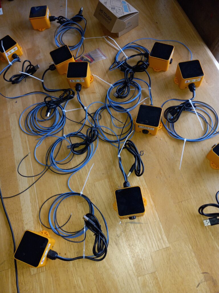
M5 Stack has some really great hardware and made this project so much smoother. 12V input signal with local status displayed on screen and also communicated to App via BLE! All based on the M5Stack Tough units.
If you’d like to subscribe to this blog, please click here.
I’ve been seeing these Arduino-based “PLCs” on the internet for a while. If you’re not familiar with PLCs, they are basically control computers with built-in or expandable Inputs and Outputs and are used for industrial control. They are typically hardened against accidental overload (too much current on the output or wrong polarity voltage on inputs) and run on 24VDC They’re built to work reliably in a harsh industrial environment. They are also usually quite expensive, although there are low-priced versions available, such as the Click PLC starting around $100 each.
There have been industrialized versions of Arduino-based controllers for years. I have built a few projects based on the Industruino, for example, and I quite like it.
But these new versions like the 10MT and the 10MR address the lower end of the market that doesn’t require that level of “toughness”. I was curious, so I picked up a couple. They’re cheap, right, so how can you go wrong?
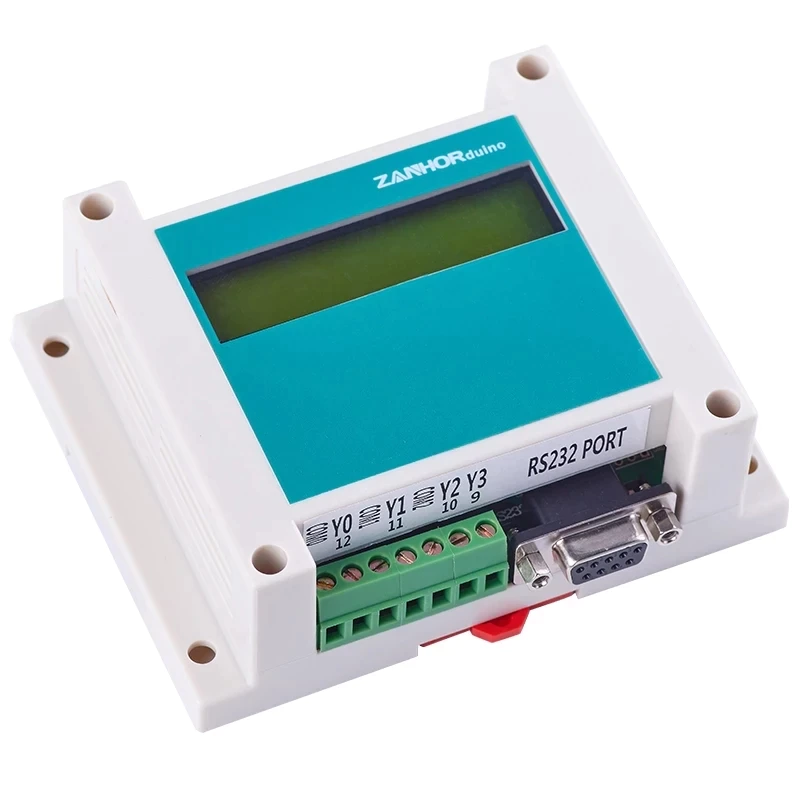
10MR PLC
First impressions are that it looks pretty good. It’s mountable either by DIN rail or four screw holes in the feet. The material seems to be ABS plastic. Polycarbonate would have been nice. Programming is via a DE-9 serial port, so you will need to connect it to a serial port. A USB-to-serial converter should work just fine. The connections are by rising-cage screw terminals, which was a nice surprise. Most Arduino clone connectors use the super cheap and annoying terminals that can’t grip wire properly unless you use ferrules. I mean, these are cheap terminals, but not the bottom of the barrel. These actually work fairly well.
The module comes with four optically-isolated FET open-drain (aka “NPN”) power-driver outputs or relays, depending on the version you choose. Outputs are labelled Y0 through Y3 and are assigned to Arduino pins 9 – 12. The 10MR has relays and the 10MT has transistors. There are also 6 digital inputs and 3 analog inputs and a 2-line, 16 character LCD. The units specify a 24VDC power supply, but I have successfully run them from 12V also.
Overview
So far I’ve only used the outputs on the 10MR and aside from a momentary surprise — the outputs are fully isolated, so you need to supply a ground and power to the load, it worked immediately to drive my test solenoid. Since it’s Arduino powered, it’s easy to control using the standard Arduino API commands.
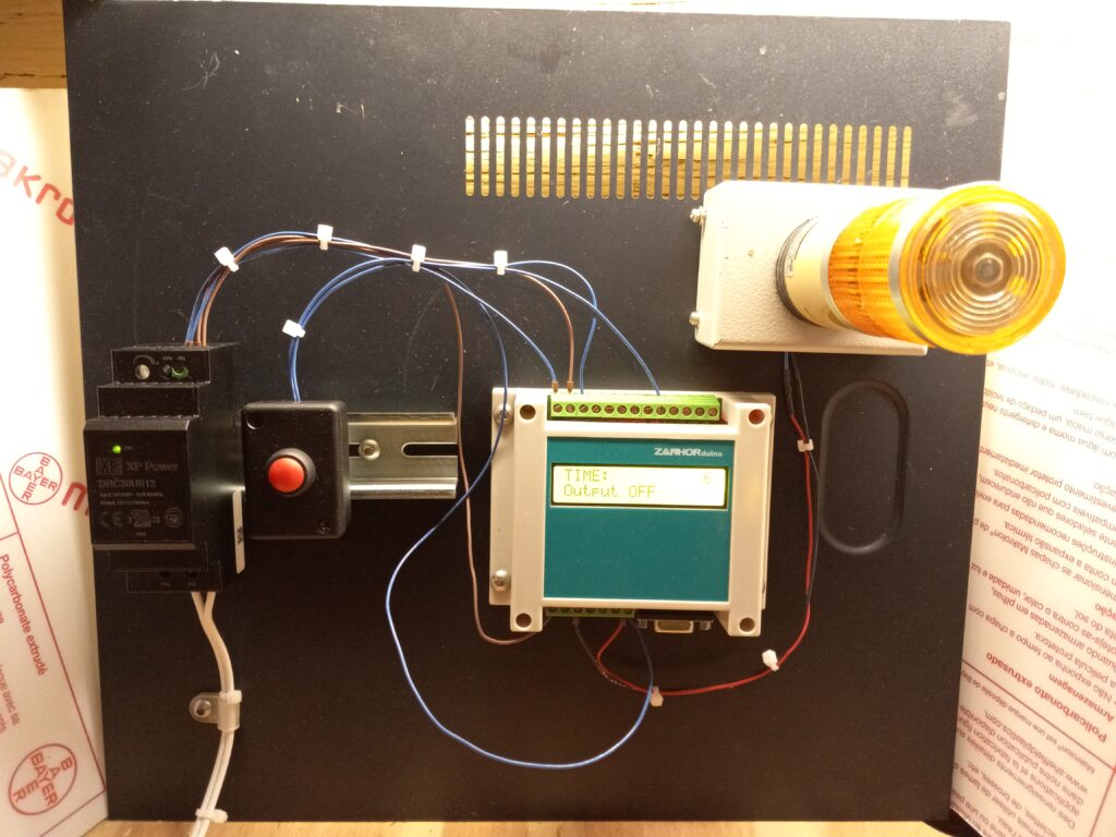
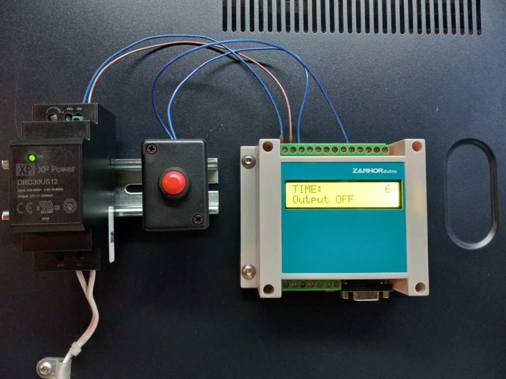
Having a display is a really nice plus, but it would be even better if there were a few pushbuttons. However, those are easy enough to add with the many digital inputs. I put together a demo platform with a power supply and a pushbutton mounted to a short piece of DIN rail and the PLC screwed directly to a panel. For output, I have a small stacklight that I converted from incandescent lighting to LED.
I ran a test with a basic one-shot timer having a pushbutton input on X0 and an output on Y0. Here’s the code.
// Project sponsor: N/A
// Email: sales@cedarlakeinstruments.com
// Creator: Cedar Lake Instruments LLC
// Date: January 2023
//
// Description:
// Demonstrate one-shot logic with Arduino
// Tested on ZanhorDuino board
//
// Arduino pins
// 9 - Digital trigger input. Pull LOW to trigger one shot
// 8 - One shot output (goes HIGH for one shot time)
//
//
// Test program for ZanhorDuino PLC
// NPN outputs are optically isolated so need their own V+ & GND connections
//

#include <Wire.h>
#include <LiquidCrystal_I2C.h>

// set the LCD address to 0x27 for a 16 chars and 2 line display
LiquidCrystal_I2C lcd(0x27,16,2);

// ********** U S E R  A D J U S T M E N T S ********************
// One shot time in milliseconds
const int DELAY_MS = 6000;
// **************************************************************

const int INTERVAL_MS = 100;
int _timeout = 0;
const bool OUTPUT_ON = false;
const bool OUTPUT_OFF = true;

// X0 is input
const int TRIGGER_PIN = 8;

// Y0 is output
const int OUT_PIN = 9 ;


void setup()
{
    pinMode(TRIGGER_PIN, INPUT_PULLUP);
    pinMode(OUT_PIN, OUTPUT);
    digitalWrite(OUT_PIN, OUTPUT_OFF);

    lcd.init();
    // Print a message to the LCD.
    lcd.backlight();
    printStatus(DELAY_MS, LOW);
}

void loop()
{
    // One shot triggers on high->low transition of TRIGGER pin
    while (digitalRead(TRIGGER_PIN) == HIGH)
    {
        // Hold while pin not pressed
    }

    // Activate output and start timing
    _timeout = DELAY_MS;
    digitalWrite(OUT_PIN, OUTPUT_ON);

    // Hold output High until timeout
    while ((_timeout-= INTERVAL_MS) > 0)
    {
        printStatus(_timeout, HIGH);
        delay(INTERVAL_MS);
    }

    // Turn output off
    digitalWrite(OUT_PIN, OUTPUT_OFF);
    // Update display
    printStatus(DELAY_MS, LOW);
}

// Prints remaining time and output status
void printStatus(int t, bool state)
{
    char buffer[17];
    // Pad to 16 characters: 12 for text (left-justified)
    // and 4 for time (right-justified)
    sprintf(buffer,"%-12s%4d","TIME:",t/1000);
    lcd.setCursor(0,0);
    lcd.print(buffer);

    lcd.setCursor(0,1);
    state ? lcd.print("Output ON ") : lcd.print("Output OFF");
}
This works nicely. Press the pushbutton and the output turns on and the display shows a countdown in seconds until the output is back off.
When I have some more time, I’ll take a look at the analog inputs!
If you’d like to subscribe to this blog, please click here.
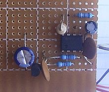 maybe you might use wire wrap or even dead-bug construction (my favorite!)