You build this really cool prop. After days, weeks, months of work, it’s done. Just one more thing: it would be so cool if that little bit on top could rotate. But how do you do that? You know motors make things move but you don’t know the first thing about motors. That’s where I come in: I know a fair amount of motors (but I don’t know a whole lot about building great-looking props…).
OK, now what?
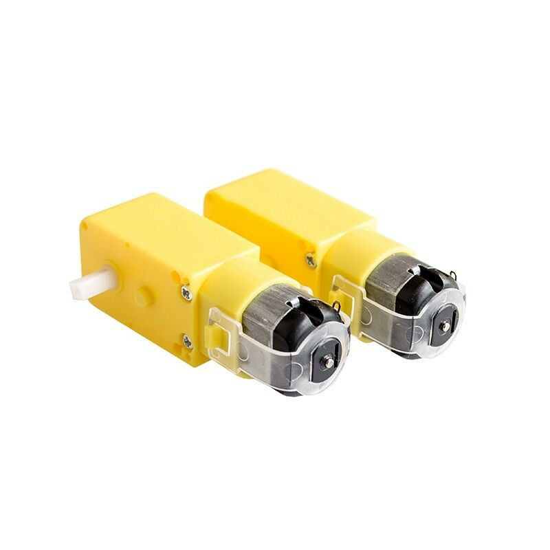
To make something move, we need a motor. Here’s a simple one to get started with.

OK, that’s actually two motors. They’re pretty cheap, so why just get one? I’m not going to post links since they’ll be outdated in seconds, but you can generally find these motors for under $5.00 each all over the web. Search “small gearmotor” and you’ll get tons of hits. These are DC gearmotors. “DC” refers to the fact that they run on Direct Current, such as what you get from a battery, as opposed to AC which is what comes from a wall outlet. A gearmotor is a type of motor that contains a gearbox. Normally, motors spin at pretty high speeds: thousands of rotations per minute(RPMs). With the embedded gearbox, we get a more useful rotation rate that’s generally between 15-100 RPM. Slower or faster speeds are available. The ones above has two output shafts that provide around 140 RPM.
OK. I’ll post one link: these guys will probably be selling them for a while
Now, any motor needs a power source. The sample ones above are small enough that they can be battery powered. Three AA’s will run them for quite a while.
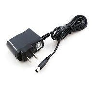
An important feature of DC motors is that their speed depends on the voltage you give them. If you run these from four AA’s they will run faster than if you ran them from two. Normally, they take 4.5 Volts, which is what you would get from the three AA’s mentioned above. If you want them to run all the time, or just don’t want to be bothered replacing batteries, you can also run them from a 5V “wall wart” power supply.

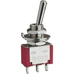
Once we have the motor and a power source, it might be nice to have an easy way to control it. This is where a switch comes in. It completes or breaks the circuit between motor and power and so turns the motor on or off.

So let’s put this all together. You know what this needs? A drawing. Drawings that electrical engineers use to show connections are called schematic diagrams. Here’s what it looks like.

As you can see there are the three elements we talked about: the battery for power supply, a motor, and a switch to turn it on and off. Look at the symbol for a switch: it shows that the contacts (1&2) are not touching. This means that the circuit is incomplete and current will not flow. When the switch is closed by pushing the shiny arm on top, those contacts will touch and complete the circuit, causing current to flow through the motor and making it move.
Enough for now? Next time we’ll wire up actual components and see how that goes.
If you’d like to subscribe to this blog, please click here.