Resistors are one of the fundamental electronic components. They fall into the category of linear devices because their behavior is predictable by a linear equation. That is, the voltage across a resistor is a linear multiple of the current passing through it:
voltage (V) = Current (i) x Resistance (R)
Important resistor characteristics
The resistance, the amount that a resistor impedes or “resists” current flow, is measured in ohms. Commonly, the Greek letter omega Ω is used as an abbreviation. e.g., a 10,000 ohm resistor is shown as 10kΩ. The power rating of a resistor is measured in Watts (W). In many applications, the power rating is important because if it is exceeded, the resistor will become very hot and physically fail, possibly even bursting into flames. For most applications in Arduino-based circuits, power is not likely to be a significant issue.
What they look like
Resistors can take a lot of different physical shapes. Here are a few examples.
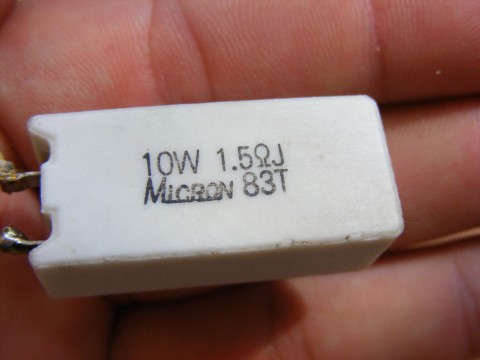
1.5ohm, 10Watt Power resistor
(By Emilian Robert Vicol from Com. Balanesti, Romania – Ceramic-Encapsulated-Resistor_23268-480×360, CC BY 2.0, https://commons.wikimedia.org/w/index.php?curid=38383544)
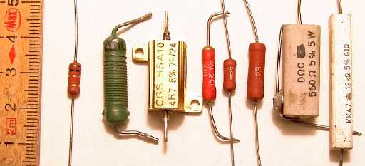
Various through-hole resistors
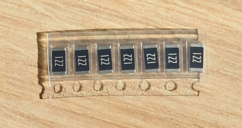
Surface-mount resistors
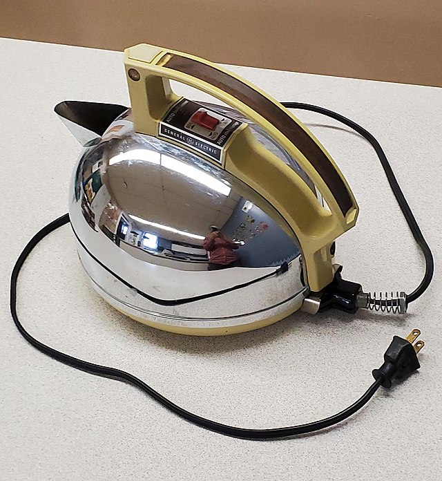
Electric kettle
Yes, an electric kettle is an example of a very high-power resistor. It uses the resistance of high-temperature wire to turn the electricity into heat.
What do we need them for?
The function of a resistor is to impede current flow. That’s it. That’s literally all they do. However, that simple statement means that they can be used for lots of different things.
Pullups/pulldowns the digital inputs to a microcontroller need to have a set HIGH or LOW state. This means that they must be fixed to the positive voltage supply (Vcc) or ground (GND). Leaving them to find their own voltage level can cause the state of the input to be constantly changing between HIGH and LOW as that floating voltage changes. A pullup or pulldown resistor is normally used if the device that is driving the input does not have a natural HIGH or LOW state. We would not want to connect the input directly to Vcc or ground, because in that case, if we were to connect the input to a signal that changes the inputs’s state, it would mean a short circuit between Vcc and ground, which is a serious problem.
One example of such a device would be a switch. Most modern processors include an internal circuit that allows the programmer to enable the input to be pulled up to Vcc, but still allows a switch or other device to drive the input to a LOW state. This is called an “internal pull up.” In many cases, an internal pull down can also be configured.
If the processor does not have built-in pull ups, or if a stronger pull up is needed (the internal ones are quite weak: on the equivalent of a 100k resistor), then an external resistor can be used in this case.
Current limiting This circuit uses a resistor to limit the current through a Light Emitting Diode (LED). Without the resistor, the LED would consume too much current and likely fail from overheating.
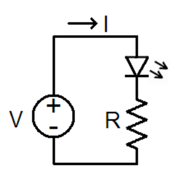
LED current limiter
A pair of resistors can reduce a voltage. In the diagram below, there are two resistors, R1 and R2. The zigzag is the standard schematic diagram symbol used to depict a resistor. Here an input voltage, Vin, is changed by the formula below to an output Vout. This circuit configuration is called a voltage divider because it divides the input voltage by a fixed amount.
If you’d like to subscribe to this blog, please click here.