I’ve been seeing these Arduino-based “PLCs” on the internet for a while. If you’re not familiar with PLCs, they are basically control computers with built-in or expandable Inputs and Outputs and are used for industrial control. They are typically hardened against accidental overload (too much current on the output or wrong polarity voltage on inputs) and run on 24VDC They’re built to work reliably in a harsh industrial environment. They are also usually quite expensive, although there are low-priced versions available, such as the Click PLC starting around $100 each.
There have been industrialized versions of Arduino-based controllers for years. I have built a few projects based on the Industruino, for example, and I quite like it.
But these new versions like the 10MT and the 10MR address the lower end of the market that doesn’t require that level of “toughness”. I was curious, so I picked up a couple. They’re cheap, right, so how can you go wrong?
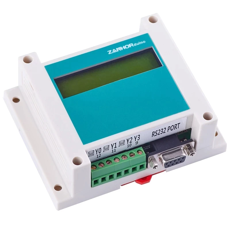
First impressions are that it looks pretty good. It’s mountable either by DIN rail or four screw holes in the feet. The material seems to be ABS plastic. Polycarbonate would have been nice. Programming is via a DE-9 serial port, so you will need to connect it to a serial port. A USB-to-serial converter should work just fine. The connections are by rising-cage screw terminals, which was a nice surprise. Most Arduino clone connectors use the super cheap and annoying terminals that can’t grip wire properly unless you use ferrules. I mean, these are cheap terminals, but not the bottom of the barrel. These actually work fairly well.
The module comes with four optically-isolated FET open-drain (aka “NPN”) power-driver outputs or relays, depending on the version you choose. Outputs are labelled Y0 through Y3 and are assigned to Arduino pins 9 – 12. The 10MR has relays and the 10MT has transistors. There are also 6 digital inputs and 3 analog inputs and a 2-line, 16 character LCD. The units specify a 24VDC power supply, but I have successfully run them from 12V also.
Overview
So far I’ve only used the outputs on the 10MR and aside from a momentary surprise — the outputs are fully isolated, so you need to supply a ground and power to the load, it worked immediately to drive my test solenoid. Since it’s Arduino powered, it’s easy to control using the standard Arduino API commands.
Having a display is a really nice plus, but it would be even better if there were a few pushbuttons. However, those are easy enough to add with the many digital inputs. I put together a demo platform with a power supply and a pushbutton mounted to a short piece of DIN rail and the PLC screwed directly to a panel. For output, I have a small stacklight that I converted from incandescent lighting to LED.
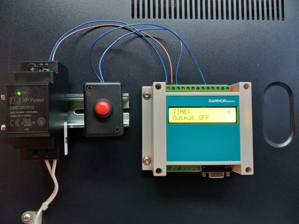
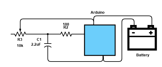
I ran a test with a basic one-shot timer having a pushbutton input on X0 and an output on Y0. Here’s the code.
// Project sponsor: N/A
// Email: sales@cedarlakeinstruments.com
// Creator: Cedar Lake Instruments LLC
// Date: January 2023
//
// Description:
// Demonstrate one-shot logic with Arduino
// Tested on ZanhorDuino board
//
// Arduino pins
// 9 - Digital trigger input. Pull LOW to trigger one shot
// 8 - One shot output (goes HIGH for one shot time)
//
//
// Test program for ZanhorDuino PLC
// NPN outputs are optically isolated so need their own V+ & GND connections
//

#include <Wire.h>
#include <LiquidCrystal_I2C.h>

// set the LCD address to 0x27 for a 16 chars and 2 line display
LiquidCrystal_I2C lcd(0x27,16,2);

// ********** U S E R  A D J U S T M E N T S ********************
// One shot time in milliseconds
const int DELAY_MS = 6000;
// **************************************************************

const int INTERVAL_MS = 100;
int _timeout = 0;
const bool OUTPUT_ON = false;
const bool OUTPUT_OFF = true;

// X0 is input
const int TRIGGER_PIN = 8;

// Y0 is output
const int OUT_PIN = 9 ;


void setup()
{
    pinMode(TRIGGER_PIN, INPUT_PULLUP);
    pinMode(OUT_PIN, OUTPUT);
    digitalWrite(OUT_PIN, OUTPUT_OFF);

    lcd.init();
    // Print a message to the LCD.
    lcd.backlight();
    printStatus(DELAY_MS, LOW);
}

void loop()
{
    // One shot triggers on high->low transition of TRIGGER pin
    while (digitalRead(TRIGGER_PIN) == HIGH)
    {
        // Hold while pin not pressed
    }

    // Activate output and start timing
    _timeout = DELAY_MS;
    digitalWrite(OUT_PIN, OUTPUT_ON);

    // Hold output High until timeout
    while ((_timeout-= INTERVAL_MS) > 0)
    {
        printStatus(_timeout, HIGH);
        delay(INTERVAL_MS);
    }

    // Turn output off
    digitalWrite(OUT_PIN, OUTPUT_OFF);
    // Update display
    printStatus(DELAY_MS, LOW);
}

// Prints remaining time and output status
void printStatus(int t, bool state)
{
    char buffer[17];
    // Pad to 16 characters: 12 for text (left-justified)
    // and 4 for time (right-justified)
    sprintf(buffer,"%-12s%4d","TIME:",t/1000);
    lcd.setCursor(0,0);
    lcd.print(buffer);

    lcd.setCursor(0,1);
    state ? lcd.print("Output ON ") : lcd.print("Output OFF");
}
This works nicely. Press the pushbutton and the output turns on and the display shows a countdown in seconds until the output is back off.
When I have some more time, I’ll take a look at the analog inputs!
If you’d like to subscribe to this blog, please click here.