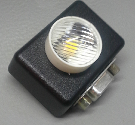
As long as we’re on a serial port kick. Here’s an easy way to read an external pushbutton or switch from your PC. Remember, that with an expensive USB to serial converter, if your computer doesn’t have an RS232 port, you can read the pushbutton switch from USB just as easily.
This is a great way to interface an external switch to your software and makes applications such as a photobooth, Lean Manufacturing cycle counter, or labwork much easier.
Like the .NET lightmeter post below, we’ll use a status control input on the RS232 port to see the switch.
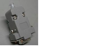
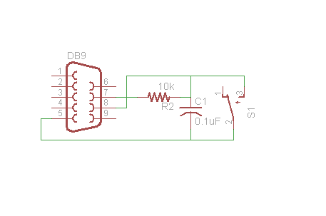
OK, you’ll need a pushbutton (of course), a resistor to hold the input line in the correct state when the pushbutton is off, a small capacitor for debouncing and a female D-sub 9 connector. And perhaps some kind of enclosure or box for the pushbutton switch if you don’t plan to mount it to an existing panel.
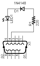
Here’s the schematic diagram:
.NET source code to read the switch and display the state is over
If you’d like to subscribe to this blog, please click here.