Occasionally you might end up in a situation where your Arduino project need to measure an analog voltage such as a thermistor or a resistance change, but all your analog inputs are in use.
Now, in this situation I would pretty much always suggest you purchase an external Analog to Digital (A/D) breakout board because they are so cheap and precise these days. But what if for some reason you can’t? Maybe you have to get this project done before one can arrive or you hit your budget limit, or, or… whatever.
There’s a very simple technique to read some analog values that you can use when all you have available are digital inputs. I won’t go into the general theory behind analog to digital conversion since there are many good ones online already. However, I will briefly talk about Single Slope Integration.
Single slope integration is a method of measuring a voltage by timing how long it takes that voltage to charge a capacitor in an R-C circuit. An R-C circuit is basically a circuit consisting of a single resistor and a single capacitor. You might remember that the voltage across the terminals of a capacitor takes time to build up. That instantaneous voltage is a function of the incoming voltage, the amount of capacitance, the resistance of the circuit and how long it’s been since the incoming voltage was applied. This last part is the bit we most care about. If we know that the capacitor is fully discharged, and we apply a fixed voltage to the input of the circuit, then the amount of time it takes that voltage to get to a specific threshold at the circuit output is a measure of the resistance value. In other words, if we keep the applied voltage constant, the capacitor value constant and the threshold constant, then the only variables are Time and the Resistance. So by measuring Time, we know resistance.
We’re going to look at an application of this technique as it was used years ago. For reference, this is how the joysticks on the original IBM PC (vintage early 80’s) worked. That should tell you how long it’s been around.
Now, before I go any further, I want to emphasize that the way we’re approaching this is not a precision measurement by any means. There are methods to make this measurement very accurate, but they generally will incur more cost than, you know, just buying an A/D breakout!
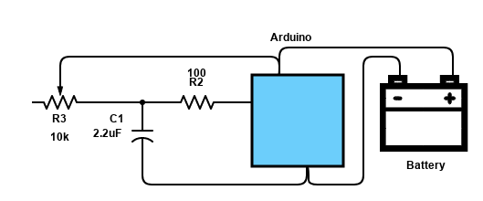
This is our circuit:
R1 is the resistance we want to get a relative value for, R2 is there to prevent damage to the Arduino pin when it tries to either charge or discharge the capacitor (a discharged capacitor looks like a dead short, so we want to limit the current going out the pin), and C1 is our capacitor. With the values shown, we should get roughly 10-bit resolution measuring a 10k ohm variable resistor.
// Simple program to illustrate reading a resistor by using a single-slope
// integration method

// Pin 2 is used as our "analog input"
// Connect R2 here
#define ANALOG_PIN 2

void setup()
{
  Serial.begin(115200);
  Serial.println("Ready");
}

void loop()
{
    // Start a reading
    pinMode(ANALOG_PIN, OUTPUT);
	// Discharge capacitor
    digitalWrite(ANALOG_PIN, LOW);
	// Wait for it to discharge
    delay(500);

	// Snapshot the start of charging
    unsigned long start = micros();

	// Use 500,000us as our timeout so this
	// doesn't hang if the resistor is disconnected
    unsigned long timeout = start + 500000;
    unsigned convEnd = 0;

	// Switch the pin to input so we can look for the
	// transition from LOW to HIGH
    pinMode(ANALOG_PIN, INPUT);

    while (convEnd = micros() < timeout)
    {
      if (digitalRead(ANALOG_PIN) == HIGH)
      {
		  // Threshold reached, exit
          break;
      }
    }

	// Resistance value is a function of the time it took
	Serial.print("Value read: ");
	// Print value read or timeout
	convEnd != timeout ? Serial.println(convEnd - start) : Serial.println("TIMED OUT");
}
So the way this works is first we discharge the capacitor through the 100 ohm resistor on pin 2. The resistor is there to limit the current and not damage the arduino. After giving it 500mS to discharge, which is plenty, now we switch the pin configuration to Input and monitor it waiting for it to transition from LOW to HIGH. At this time, we break out of the loop and report the time difference between start and conversion end. This is proportional to resistance.
For better performance, you can calibrate the software by using two known-value resistors in place of R1 to measure a min and max conversion time. Once you have that, you can interpolate between those values to measure any unknown resistor value.
If you’d like to subscribe to this blog, please click here.