Let’s say you’re using a comparator like the venerable old LM339. You provide a setpoint “reference” and an input. If the input is below the setpoint, the output is clamped to ground. If the output is above the setpoint (plus any offset voltage of the comparator, of course), the open-collector output floats. Normally we tie the output to +5V if we want a TTL level output as we are often using the comparator to send a signal to a digital or microcontroller circuit. With me so far? OK.
The classic voltage divider is a good choice for a setpoint if it only needs to stay constant. But what if you need a variable setpoint? Simple, use a trimmer, trimpot, variable potentiometer, whatever you wanna call it. Now you can change the voltage of the setpoint. But wait a minute. If we have a regulated 12VDC and use a trimpot, even an expensive multiturn, it can still be difficult to set that voltage to within a millivolt. After all, a 10-turn pot with 12V at the input is still 1.2 volt per revolution, so with 360 degrees per revolution, you’d need fingers precise to almost 1/3 of a degree to set it to within a millivolt. Possible, but difficult.
Like most things, there are multiple ways to skin this particular cat (I can only write this while Lefty and Poncho are not in the room…).

In the olden, golden days, engineers with beards and slide-rules used verniers that geared the output down, so one turn of the knob might only be 1/10th turn of the potentiometer on the output.
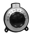
This makes it easier to adjust, but those things are $$$. Gotta be a cheaper solution. Sure, use a voltage divider. Remember the divider can take an input voltage and give you a smaller output, but if we make the divider variable, we can make it so we only vary it by a small amount. So instead of trying to adjust a 0-5 volt range with a potentiometer, we can design the divider so we only have to adjust a 0 – 0.1V range with the same pot. Much easier!
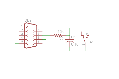
Say Vin is 12V, R1 is 10k and R2 is 820Ω. Vout is then 0.91V. If we insert a 1k potentiometer between R1 & R2,that means that the output can now vary about that point.
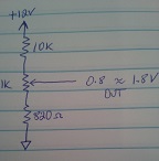
So, how does this work? Let’s assume the pot is all the way in one direction, the voltage divider is then 1,820÷11,820 x 12 = 1.85V
with the pot all the way in the other direction, the output is 820÷11,820 x 12V = 0.83V
Nice! So now our trimpot only has to control a span of about 1V instead of a span of 12V. With high-resolution A/D converters and digital inputs, these basic techniques aren’t used a lot these days, but they are still useful to have in your toolbox.
Now go design something!
If you’d like to subscribe to this blog, please click here.