Categories
Uncategorized

Reading temperature on BeagleBone with AD592

A very common task is to measure temperature at various points. In fact, temperature is the most commonly measured and controlled variable in Process Control. The BeagleBone single-board computer is becoming more popular because of its low cost and sophisticated capabilities. It’s one of the easiest ways to serve up a web page that allows the operator to monitor data and control devices.

Temperature can be measured with a variety of sensors. Here we are concerned with the range of liquids from around 0C to 80C. A straightforward way to measure temperatures in this range is with a semiconductor analog-output sensor. They are easy to use, accurate, and low cost.

I happened to have a number of AD592 temperature to current sensors on hand. These have been traditionally used for process control because their current output makes them very noise resistant when long cable are used. We convert the current (1 microvolt/Kelvin) to a voltage by using a resistor. In this case, we use a 3.3kohm resistor to produce a voltage of around 1V at room temperature. The 3.3k resistor gives a resolution of .003V/Kelvin which with the 273.15K offset gives 0.003V/degree Celsius.

Using the sensor connected to 5V, AGND and the analog input on P9, pin 36, we use this code snippet to read the sensor:

// Read an AD592 temp sensor and return degF
function readTemp()
{
   var volts = 1.8 * trap.analogRead("P9_36");
   // Convert to Kelvin. AD592 outputs 1uV/K
   var k = volts / 3300 / 0.000001;
   // Convert to Fahrenheit
   var f= (k - 273.15) * 9 / 5 + 32;
   // Log the measured values
   console.log("V,k,F: " + volts,k,f);
   return f;
}

For improved accuracy we can measure the actual resistance of the 3.3k resistor and use that measured value in the program.

This concept is easily extended to remote reading. Since the BeagleBone is a powerful little Linux computer, it can be used to serve web pages. We have a simple node.js webserver and sensor data reader program available at this download link


If you'd like to subscribe to this blog, please click here.
Categories
Arduino

Arduino Programming: hydraulic shock control from pushbutton

This was a response to an online request for help with code. A single  pushbutton cycles through three hydraulic damper valve settings. The code was too long to post on the site, so I’m showing it here.

As of today, I don’t know if it will work, but it explains the concept. I will get it working as time permits

// Digital output definitions
#define RED_OUTPUT 0
#define BLUE_OUTPUT 1
#define GREEN_OUTPUT 2

// Digital input definitions
#define SWITCH_INPUT 3

// Define states
#define RED 800
#define BLUE 801
#define GREEN 802

// Define message types
#define NONE 901
#define CLICK 902
#define PRESS 903
   
// Global state
int _state = GREEN;

// One-time call to initialize system
void setup()
{
   pinMode(SWITCH_INPUT, INPUT_PULLUP);
   pinMode(RED_OUTPUT, OUTPUT);
   pinMode(BLUE_OUTPUT, OUTPUT);
   pinMode(GREEN_OUTPUT, OUTPUT);
   // Enable GREEN state
   digitalWrite(GREEN_OUTPUT, HIGH);
}

// Continuously called by Arduino runtime
void loop()
{
   // Read pushbutton
   int message = readSwitch();
   // Update LEDs and hydraulic valve if state changed
   if (processState(message))
   {
      activateOutput(_state);
   }
}

// Read pushbutton and return the result
int readSwitch()
{
   const int CLICK_UPPER_LIMIT = 200;
   const int CLICK_LOWER_LIMIT = 25;
   const int PRESS_LOWER_LIMIT = 1000;
   const int PRESS_UPPER_LIMIT = 2000;

   int switchMessage = NONE;
   unsigned long start = micros();
   while (digitalRead(SWITCH_INPUT) == LOW);
   unsigned long duration = micros() - start;
   if (duration < CLICK_UPPER_LIMIT && duration > CLICK_LOWER_LIMIT)
   {
      switchMessage = CLICK;
   }
   else if (duration > PRESS_LOWER_LIMIT && duration < PRESS_UPPER_LIMIT)
   {
      switchMessage = PRESS;
   }
   return switchMessage;
}

bool processState(int message)
{
   static int lastState = GREEN;
   int retVal = 0;

   // PRESS overrides CLICK in all states
   if (message == PRESS)
   {
      _state = GREEN;
   }
   else
   {
      // Process states
      switch (_state)
      {
         case RED:
            if (message == CLICK)
            {
               _state = BLUE;
            }
         break;
            
         case BLUE:
            if (message == CLICK)
            {
               _state = RED;
            }
         break;
            
         case GREEN:
            if (message == CLICK)
            {
               _state = RED;
            }
         break;
            
         default:
         break;
      }
   }
   // Did state change?
   retVal = (lastState == _state);
   // Remember this state
   lastState = _state;
   // Return state changed information
   return retVal;
}

void activateOutput(int thisState)
{
   // Since this is only called on state change, OK to turn everything off first
   digitalWrite(RED_OUTPUT, LOW);
   digitalWrite(GREEN_OUTPUT, LOW);
   digitalWrite(BLUE_OUTPUT, LOW);
   // Turn on only the output corresponding to the state
   switch (thisState)
   {
       case RED:
         digitalWrite(RED_OUTPUT, HIGH);
         break;         
       case BLUE:
         digitalWrite(BLUE_OUTPUT, HIGH);
         break;      
       case GREEN:
         digitalWrite(GREEN_OUTPUT, HIGH);
         break;
      default:
         break;
   }   
}


If you'd like to subscribe to this blog, please click here.

Categories
Uncategorized

Control a small DC pump

In an earlier post I showed how to wire a small DC pump to a power supply and a switch to turn it on and off. Even with simple manual control, there are still things to be aware of. Let’s say that you are building a small aquaponic or hydroponic system and you need a pump to circulate nutrient fluid to the plant roots. This is a situation where the pump only needs simple on/off control and can be left to run continuously.

There is a danger that over time the liquid will evaporate and its level will drop too low. Many liquid pumps cannot safely be run dry. This is because they are designed to use the liquid flowing through to cool them to a normal operating temperature. Without a continuous fluid flow, the motor will overheat.

This means we have to be aware of the liquid level. A float switch level sensor can be used in the control circuit to make sure that the pump does not run when the liquid is below a certain level. Most liquid level switches can’t control the current needed to run a pump so we use the switch to control a relay that has this needed current capacity.

It’s also important to remember that some pumps also have a maximum on-time rating. The pump may be able to run only (e.g.,) one minute continuously before it needs to be turned off to cool for three minutes. This proportional on/off time is referred to as its duty cycle.


If you'd like to subscribe to this blog, please click here.
Categories
pumps

Wiring a small DC pump

Using low voltage DC pumps is a safer way to become involved in flow control. Direct Current (DC) is generally simpler to control than Alternating Current (AC) and the low voltages are much safer than the 120 volts AC coming out of a wall outlet.

Your DC pump will have two leads and the proper polarity must be observed. That means that the positive and negative connections must not be swapped. DC pumps come in two styles: brushed and brushless. Most newer pumps are brushless. A primary advantage of a brushless motor is that it is normally quieter and generates less electrical interference. However, because the motor generally incorporates an electronic controller, it can be damaged if the power leads are reversed. So be careful. By contrast, reversing the power leads on a brushed motor pump will usually only cause the pump to not run properly (the motor will run backwards), but not cause damage.

To power the motor a source of DC at the proper voltage and supplying enough current is needed. Often this can be as simple as a “wall wart.”

wart-smallMore reliable industrial power supplies are also available. Use a power supply that can provide at least as much current as your pump needs. A greater current capacity is not a problem. This means that if, for example, your pump is rated 12VDC @ 0.5A, a 12VDC power supply with 10A capacity is perfectly safe. However a 24VDC supply rated for 0.5A may cause the motor to run too hot and eventually burn up.

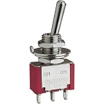
You will also need a method to turn the motor on and off. Most small low voltage DC pumps can be controlled directly from a switch.

toggle-small    It is a good idea to use a fuse inline with larger pumps (2A+). This way, if the pump jams due to debris, etc. in the line, it will blow the fuse instead of damaging itself due to overheating


If you'd like to subscribe to this blog, please click here.
Categories
Uncategorized

Why RS-232 serial?

Why do we use RS232 serial ports to communicate with our hardware? Well, first and foremost, it is probably the least-common-denominator communication method in the industrial and embedded physical computing arena. If a computer has just one port, odds are it’s a serial port. This is mainly because serial ports are so easy to implement.

Those computers that don’t have RS232 serial ports, will usually have USB (another serial bus) ports. Because of the decades-long history of RS232, USB to RS232 ports are easy to find. Nothing wrong with USB, but it has more complexity and is limited to fairly short distances.

So, in a nutshell, RS232 serial ports are easy to work with, ubiquitous and reliable.


If you'd like to subscribe to this blog, please click here.

Categories
Uncategorized

Detecting when water flow stops

Flowmeters are used to measure liquid flow. However, if you only need a notification that flow is present or not and don’t need to know the quantity of liquid, there are simpler methods.

A flow switch is an on/off device that will indicate whether or not a liquid is moving. They can be either Normally Open (NO), meaning that the switch is not conducting when there is no flow, or Normally Closed (NC) meaning that the switch is conducting when there is no flow. Having both types available offers flexibility to a design. One of the nice things about a flow switch is that is is very simple to build a visual indicator of whether the liquid is flowing or not. By using a light (bulb or LED) or a buzzer and a flow switch you can build a simple low flow alarm.

They are available in various pressure ratings that set the threshold of flow/no flow.

Flow switches generally present less resistance to flow than a flow meter, so there is less pressure loss across the switch.

As with flowmeters, our PRT232 is an easy way to read a flow switch and get an indication of fluid flow into your PC via an RS232 serial connection.


If you'd like to subscribe to this blog, please click here.
Categories
Uncategorized

More on LEDs

The post on how to (light an LED from an RS232 serial port) got more interest than I expected. There is an old design that I played around with a couple years ago for a high-power RS232 serial port LED light that I am thinking of resurrecting. It’s so bright, it hurts to look directly into it! A USB version might also be nice, but RS232 has a great advantage in distance and most of the people we talk with need something more rugged than USB. You can run serial lines to the LED controller for over 100 feet under good conditions. The only thing that really competes with that is wireless or Ethernet.

Note to self: Ethernet LED controller? Hmmm.


If you'd like to subscribe to this blog, please click here.

Categories
Uncategorized

How to connect a switch or push button to PC

As long as we’re on a serial port kick. Here’s an easy way to read an external pushbutton or switch from your PC. Remember, that with an expensive USB to serial converter, if your computer doesn’t have an RS232 port, you can read the pushbutton switch from USB just as easily.

This is a great way to interface an external switch to your software and makes applications such as a photobooth, Lean Manufacturing cycle counter, or labwork much easier.

Like the .NET lightmeter post below, we’ll use a status control input on the RS232 port to see the switch.

OK, you’ll need a pushbutton (of course), a resistor to hold the input line in the correct state when the pushbutton is off, a small capacitor for debouncing and a female D-sub 9 connector. And perhaps some kind of enclosure or box for the pushbutton switch if you don’t plan to mount it to an existing panel.

Here’s the schematic diagram:

DB9-SW

.NET source code to read the switch and display the state is over

here


If you'd like to subscribe to this blog, please click here.
Categories
Uncategorized

Serial Port LED flasher

Need a simple software controlled indicator? A green light when there’s unread email in your inbox? Red flashing alarm showing that the last nightly software build is broken? Or perhaps you really need a “do not disturb” sign that you can control without leaving your keyboard.

serial-led

Software-driven indicator lights are one of those things that seem like they should be simple — and they are. The problem is that today’s computers make them more difficult than before. “Once upon a time” every PC had a parallel printer port and it was the doorway to thousands of I/O devices back in the day. Today, USB is dominant and it takes a bit more than a simple out() or in() command in C to get access to the outside world from the desktop computer. This is probably why we see so many hackers turning to Arduinos to do such a simple task: it’s what’s available and well known. The problem is that it’s overkill and requires that you learn yet another toolkit.

A very simple way to control an LED is from a computer’s serial RS232 port. While few new PCs are coming with RS232 ports, they all have USB ports and USB to RS232 adapters are a dime a dozen. Or at least not much more than $5. So here’s how to get an RS232 LED indicator working.

We can hang a modern high efficiency LED off one of the RS232 data flow control lines and control it by software. Microsoft .NET, the Win32 API and Linux all offer libraries to control the serial port.

OK, enough talk, here’s a schematic:

DB9-LEDFour components: one of which is more for warm fuzzies than anything else. Pin 5 on the RS232 adapter is ground and pin 4 is the Data Terminal Ready (DTR) control line. R1 is used to limit current to the LED. Depending on the serial port, the voltage at pin 4 may range from -12V to +12V. Since the reverse voltage on most LEDs tops out at around -5V, we add a signal diode to give more reverse voltage protection. For most USB-serial adapters on the market, this probably isn’t needed, since their voltage tends to not drop below -5V, but let’s be safe. R1 can be adjusted depending on the color of the LED and how bright you need it to be. In this circuit, it’s about as low as I’d consider safe: with a red LED the circuit will draw about 10mA, which is about as much as most common serial translator chips will safely provide. It works with the adapters I’ve tested, but a safer value would be around 470 ohms. The limiting factor is the drive of whatever chip is powering the RS232 lines. USB itself can provide much more current than we need here.

You can build your own from the diagram shown above if you have the parts and experience. If you just need to get to the end result right away, we provide the complete unit shown in the picture below for $14.98 (shipping included) It drives a high-brightness white LED directly from a PC serial port (or USB-serial adapter). Complete documentation on programming it with the .NET SerialPort class is included along with a sample program written in C#. If you would like to see the code, it is on GitHub at this repository.

db9-LED
Serial LED controller………………….$14.98


This product has been discontinued.


If you'd like to subscribe to this blog, please click here.
Categories
Uncategorized

Making connections – the end of the wire

So now that we know a little about wire, what are we connecting?

Much like wire and wire gage, the type of connector is often an outcome of what needs to be connected to what. The “trick” here is to know what is commonly used in a situation similar to yours, and purchase that. For example, the signals sent from an MP3 player to headphones are at a similar level to say, a temperature sensor’s signal. So, if you need to connect the three terminals of a temperature sensor (power, ground and signal), using a standard stereo headphone jack and mating connector would be a good place to start. Easy to source, cheap to purchase and will work for most cases.

Likewise, for a small number of higher current conductors, the common PC power supply connectors are inexpensive and easily found at most parts distributors.

The type of signals most of our customers are working with are generally a good fit for the variety of DIN connectors: these are easy to find for between two to eight conductors and since they are popular in the professional audio field, are generally inexpensive. They also have the benefit of being very easy to use; just decide how many contacts you need, and go. No special tools or separate contact, housings, strain reliefs, etc. need to be purchased.

For maximum versatility, we like Circular connectors.

CIR_Connector

These are often referred to as “Cannon” connectors from the company who popularized them for industrial and military use. Their use spans the range from very low level millivolt signals, to high voltage, high current applications.

Circular Plastic Connectors are less expensive than the metal versions, but retain the versatility. They can be complex since you need to match the connector shell with the appropriate pin size, perhaps add a backshell, cable clamp or seal, and decide on crimp or solder type connectors. But if you need to securely connect a few dozen signals in a harsh environment, they are definitely worth a look.


If you'd like to subscribe to this blog, please click here.