Arduinos are popular small microcontroller boards that have many applications. However, they’re not designed to switch loads above a few milliamps: say a couple LEDs or so. While power-driver shields do provide this capability, they also can consume more resources than you may be able to give up.
We developed a high current driver to make it easy to control a solenoid valves with Arduino. It will also control pumps and motors. With an adapter cable, it can easily connect to your Arduino, BeagleBone, Raspberry Pi or other digital controller without soldering or crimping any connections. Doesn’t get any easier than that.
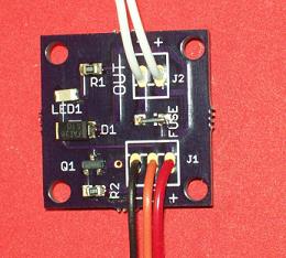
The power driver board was born out of a need for controlling a 1 amp solenoid valve using an Arduino. The solenoid valve was being used to control the water flow to fill a tank automatically. Now there’s a simple way to use your Arduino or compatible to switch up to 3A at 24VDC. Two output connections (the white wires shown above) connect directly the load (your solenoid, relay, motor, etc) and the power (red, black) go to the power supply (5 -24 volts). The orange lead is used to switch on and off. This is a low-voltage (5V) control that can connect directly to a microcontroller, or development board. An onboard LED indicates when the load is switched on.
Here’s some sample code that implements a timer with an Arduino. When the pushbutton is pressed, it turns on water flow for 3 seconds
// This sketch demonstrates a simple timer
// A load (motor, solenoid, relay, solenoid valve is on Pin 1
// A pushbutton to trigger the timer start is on pin 2
//
// When the pushbutton is held down for more than 0.1 second
// then released, the timer starts
// and times out after 3 seconds
//
// Timer is retriggerable: if pushbutton pressed
// during the timeout period, timer restarts
//
// Constant definitions
#define LOOP_INTERVAL 10
#define TIMEOUT 300 * LOOP_INTERVAL
#define TRIGGER_INTERVALS 10
#define TIMER_INACTIVE -1
#define TRIGGER_PIN 0
#define OUTPUT_PIN 1

void setup()
{
  pinMode(OUTPUT_PIN, OUTPUT);
  pinMode(TRIGGER_PIN, INPUT_PULLUP);
}

void loop()
{
  static int count = 0;
  static int timer = TIMER_INACTIVE;
  // Process loop periodically
  delay(LOOP_INTERVAL);

  // Check trigger input
  if (digitalRead(TRIGGER_PIN) == LOW)
  {
    // Must hold down pushbutton for the entire interval and
    // then release to trigger
    count++;
  }
  else
  {
    // push button released. Check if we should start timing
    if (count >= TRIGGER_INTERVALS)
    {
      // Turn output ON (timeout is retriggerable)
      digitalWrite(OUTPUT_PIN, HIGH);
      timer = TIMEOUT;
    }
    count = 0;
  }

  // If timer active, count down
  if (timer != TIMER_INACTIVE)
  {
    timer -= LOOP_INTERVAL;
    if (timer == 0)
    {
      // Turn output OFF
      digitalWrite(OUTPUT_PIN, LOW);
      timer = TIMER_INACTIVE;
    }
  }
}
Let’s find out what new applications you can come up with.
![]()
If you'd like to subscribe to this blog, please click here.