Step 2:
If you'd like to subscribe to this blog, please click here.
Occasionally you might end up in a situation where your Arduino project need to measure an analog voltage such as a thermistor or a resistance change, but all your analog inputs are in use.
Now, in this situation I would pretty much always suggest you purchase an external Analog to Digital (A/D) breakout board because they are so cheap and precise these days. But what if for some reason you can’t? Maybe you have to get this project done before one can arrive or you hit your budget limit, or, or… whatever.
There’s a very simple technique to read some analog values that you can use when all you have available are digital inputs. I won’t go into the general theory behind analog to digital conversion since there are many good ones online already. However, I will briefly talk about Single Slope Integration.
Single slope integration is a method of measuring a voltage by timing how long it takes that voltage to charge a capacitor in an R-C circuit. An R-C circuit is basically a circuit consisting of a single resistor and a single capacitor. You might remember that the voltage across the terminals of a capacitor takes time to build up. That instantaneous voltage is a function of the incoming voltage, the amount of capacitance, the resistance of the circuit and how long it’s been since the incoming voltage was applied. This last part is the bit we most care about. If we know that the capacitor is fully discharged, and we apply a fixed voltage to the input of the circuit, then the amount of time it takes that voltage to get to a specific threshold at the circuit output is a measure of the resistance value. In other words, if we keep the applied voltage constant, the capacitor value constant and the threshold constant, then the only variables are Time and the Resistance. So by measuring Time, we know resistance.
We’re going to look at an application of this technique as it was used years ago. For reference, this is how the joysticks on the original IBM PC (vintage early 80’s) worked. That should tell you how long it’s been around.
Now, before I go any further, I want to emphasize that the way we’re approaching this is not a precision measurement by any means. There are methods to make this measurement very accurate, but they generally will incur more cost than, you know, just buying an A/D breakout!
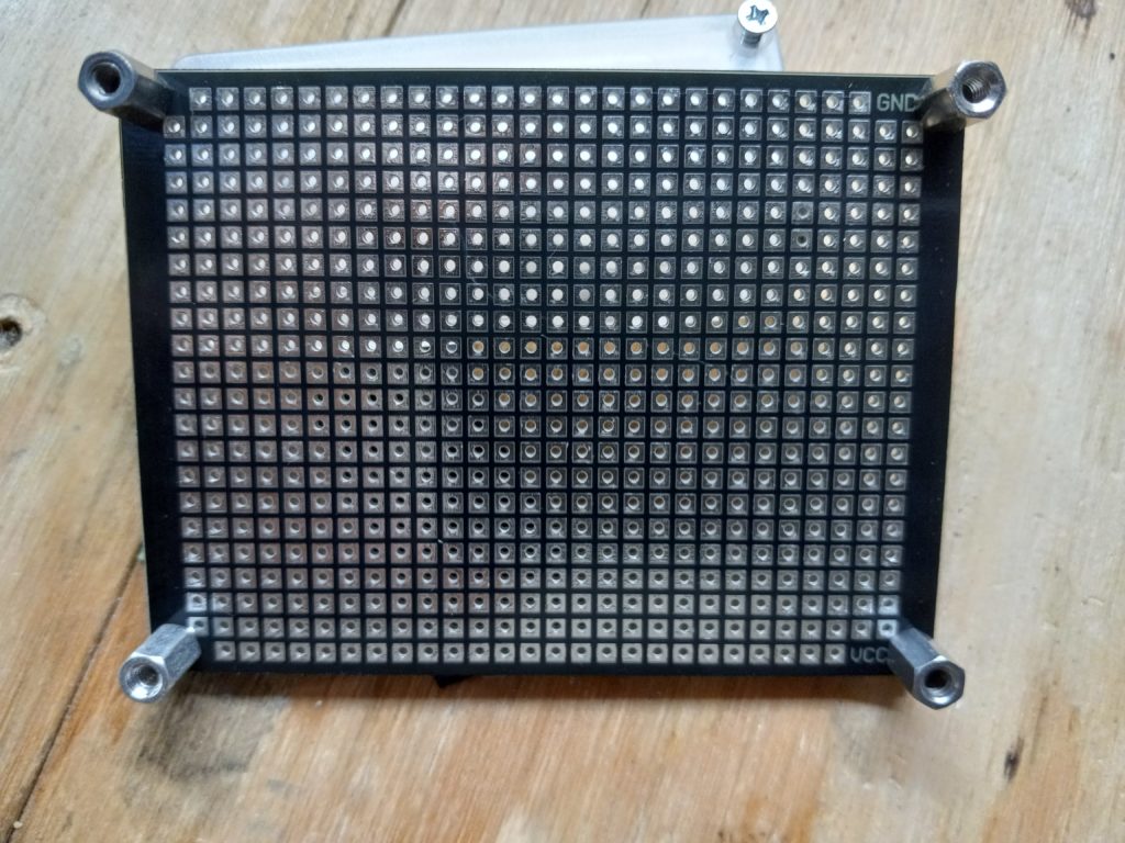
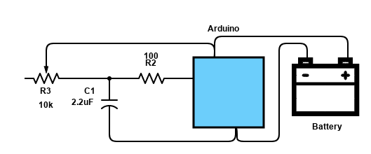
This is our circuit:
R1 is the resistance we want to get a relative value for, R2 is there to prevent damage to the Arduino pin when it tries to either charge or discharge the capacitor (a discharged capacitor looks like a dead short, so we want to limit the current going out the pin), and C1 is our capacitor. With the values shown, we should get roughly 10-bit resolution measuring a 10k ohm variable resistor.
// Simple program to illustrate reading a resistor by using a single-slope
// integration method

// Pin 2 is used as our "analog input"
// Connect R2 here
#define ANALOG_PIN 2

void setup()
{
  Serial.begin(115200);
  Serial.println("Ready");
}

void loop()
{
    // Start a reading
    pinMode(ANALOG_PIN, OUTPUT);
	// Discharge capacitor
    digitalWrite(ANALOG_PIN, LOW);
	// Wait for it to discharge
    delay(500);

	// Snapshot the start of charging
    unsigned long start = micros();

	// Use 500,000us as our timeout so this
	// doesn't hang if the resistor is disconnected
    unsigned long timeout = start + 500000;
    unsigned convEnd = 0;

	// Switch the pin to input so we can look for the
	// transition from LOW to HIGH
    pinMode(ANALOG_PIN, INPUT);

    while (convEnd = micros() < timeout)
    {
      if (digitalRead(ANALOG_PIN) == HIGH)
      {
		  // Threshold reached, exit
          break;
      }
    }

	// Resistance value is a function of the time it took
	Serial.print("Value read: ");
	// Print value read or timeout
	convEnd != timeout ? Serial.println(convEnd - start) : Serial.println("TIMED OUT");
}
So the way this works is first we discharge the capacitor through the 100 ohm resistor on pin 2. The resistor is there to limit the current and not damage the arduino. After giving it 500mS to discharge, which is plenty, now we switch the pin configuration to Input and monitor it waiting for it to transition from LOW to HIGH. At this time, we break out of the loop and report the time difference between start and conversion end. This is proportional to resistance.
For better performance, you can calibrate the software by using two known-value resistors in place of R1 to measure a min and max conversion time. Once you have that, you can interpolate between those values to measure any unknown resistor value.
If you'd like to subscribe to this blog, please click here.
Bill acceptors and coin acceptors are used to take cash payments. They work by detecting certain denominations of bills or coins and provide an output signal that can be read by a computer. This allows your software to take cash payments. We’ve had a few inquiries from owners of the popular NV9 bill acceptor and how it can be interfaces using our counter systems.
This is a quick note for those using the NV9 bill acceptor. As we mentioned in an earlier post, our PRT232 or IOCTL counters can give your PC the ability to record the cash value of bills inserted into a bill validator. Recall that the IOCTL232 is the same as the PRT232 but without an enclosure and at a lower cost. With the NV9 bill validator specifically, pins 1 & 16 on the main interface connector are used for the connection to the PRT232 “sensor” connector. Pin 16 is ground and pin 1 is the open-collector pulse output.
The pulses are delivered at a rate of about 10 per second, which is well within the counting speed we support. The dollar values are sent as 1 pulse per dollar, e.g., a $1 bill produces one pulse, a $50 produces 50 pulses and so on.
If you'd like to subscribe to this blog, please click here.
We are getting ready to release a new high speed counter that greatly simplifies machine to PC connections.
Feature set:
The device implements USB counter that is significantly faster than our existing ones and it is still compatible with the existing software interface.
This counter has a maximum input pulse rate of 20MHz and will accept either a “standard” or Gray-code mode used for interfacing with quadrature encoders. You can now get a high speed quadrature encoder input read from your PC’s USB port. This new high speed interface is available in a choice of DIN-rail mount or standard wall/desktop mounting enclosure.
Click the link below to be notified when the interface is available for the introductory $125 pricing. This price is only available for pre-orders.
If you'd like to subscribe to this blog, please click here.
I wrote this a long time ago for someone who disappeared. Hope it’s useful to you.
int ledPin1 = 9;
int ledPin2 = 10;
int ledPin3 = 11;

#define THRESHOLD 90
#define FLICKER 250
#define OFFSET 5;
#define DLY 100

int _levels[] = {0,0,15,10,15,20,25,30,50,75,100,500,700,1000};

void setup()
{
}

void loop()
{
    int len = sizeof(_levels)/sizeof(int);
    int level1 = _levels[random(len-1)];

    analogWrite(ledPin1, level1);
    if (level1 > THRESHOLD)
    {
 //      analogWrite(ledPin2, random(FLICKER));
    }
    else
    {
  //      analogWrite(ledPin2, 5);
    }

    //analogWrite(ledPin3, random(FLICKER)+OFFSET);
    delay(random(DLY));
}
If you'd like to subscribe to this blog, please click here.
A few months ago I was asked to build a custom counter. I get that request fairly often, but this one was different. The thing that needed to be counted was the transition of a thin line past the sensor. The feature to be counted was about 0.5mm thick. It was a black line on a yellow background so at least the contrast was pretty good. Since the counter needed to be portable and could not be attached to the equipment containing the feature to be counted, we figured that a way to visually align the sensor to the line was best. This meant that the sensor would emit visible light, so it would be possible to see when the light was in the right spot.
Since a 0.5 thin line is in the realm of barcode line decoding, I looked for sensors used in barcode readers. Problem is, that they are rarely specified that way. All I could find were 2D barcode sensors/cameras and those were overkill for my purpose. Oh, well!
So I figured that what made the most sense was a sensor with a small field of view. That way it could provide the highest signal to noise ratio (SNR).
I tried a number of sensors but the one that offered the best performance was the Optek OPB70DWZ. Having a red LED meant it was easy to tell when it was correctly positioned to “see” the feature. We found that the optimal distance from sensor to object was about 4mm. At that distance it worked quite reliably. The sensor was biased with a 4.7k ohm resistor to +5V. I found that by varying the bias, I could affect the sensitivity and adjust it for best SNR.
The counter itself had some logic to control the machine whose behavior was being counted, and it also required a display to show the count and to indicate what the current machine state was, so I did not use one of our existing RS232 counters. Instead I created a custom application based on an Arduino Nano and it’s worked quite well. The customer appears quite pleased with its performance.
The usual disclaimer: we’re not affiliated with Optek, but very happy with the performance. I’m posting this here because when looking for an optical sensor that could detect very small features or lines, nothing useful was returned from my searches. Hopefully this helps someone in the future.
If you'd like to subscribe to this blog, please click here.
I recently posted this on Reddit, but after feedback I figured it would be useful here also. Over the years, I’ve accumulated some knowledge about assembling Printed Circuit Boards (PCBs) and it never occurred to me that everyone hasn’t gone through the same school of hard knocks that I have. So here are a few tips when assembling boards.
Here are some of the things I learned over time:
If you'd like to subscribe to this blog, please click here.
Here is an easy way to start a program for a Raspberry Pi with a Graphical User Interface automatically on boot up.
We’re assuming you are using a recent distro like Raspbian Buster. The autostart folder under ~/.config is where the file goes. The command file format to start your program is:
[Desktop Entry]
Type=Application
Name=HelloWorld
Exec=/usr/bin/python ~/hello.py
Save this file in the autostart folder and call it hello.desktop. This will start a simple “HelloWorld” type program (hello.py) written in Python with a Tkinter GUI framework. It’s probably as simple as it can get.
If you need to run Python under lighttpd, there’s a good tutorial over here.
If you'd like to subscribe to this blog, please click here.
What was once unthinkable has now happened: you can run software written for Microsoft’s .NET framework on Linux. This means you can now write code in Visual Studio on a PC that can be executed on a pi running Linux.
The process is pretty simple. Let’s start by assuming you have Visual Studio (at least the 2017 version) and a current version of the .NET SDK on your host computer. You can download that from Microsoft here.
Open a new command shell and create a directory called blinky.
Go to the directory: cd blinky.
Type the command dotnet new console
This creates a Visual Studio project called blinky. Replace the Program.cs file with our sample code (TBD) to blink an LED.
Build the program for Linux with the command dotnet publish -r linux-arm
We now have an application package in the publish subdirectory that we can load onto a Raspberry Pi running Linux. Let’s get the pi setup to run .NET Core. We’re going to assume that it’s running Raspbian Debian 9 Jessie since that’s current as this is written.
sudo apt-get install curl libunwind8 gettext apt-transport-https
sudo apt-get update
After the .NET Core framework has been installed, copy the publish directory from your PC to the pi and execute the blinky.exe program to run it. Enjoy your blinking LED!
Here is the source code of the blinky Program.cs
using System;
using System.Threading;
using System.Device.Gpio;

namespace blinky
{
    // Blinks an LED on GPIO pin 16 on a Raspberry pi
    class Program
    {
        static void Main(string[] args)
        {
            Console.WriteLine("Hello World!");
            int pin = 16;
            GpioController controller = new GpioController();
            controller.OpenPin(pin, PinMode.Output);

            int lightTimeInMilliseconds = 1000;
            int dimTimeInMilliseconds = 200;

            while (true)
            {
                Console.WriteLine($"Light for {lightTimeInMilliseconds}ms");
                controller.Write(pin, PinValue.High);
                Thread.Sleep(lightTimeInMilliseconds);
                Console.WriteLine($"Dim for {dimTimeInMilliseconds}ms");
                controller.Write(pin, PinValue.Low);
                Thread.Sleep(dimTimeInMilliseconds);
            }
        }
    }
}
If you'd like to subscribe to this blog, please click here.
OK, so this wasn’t the first experiment but it was the first one I recorded. I’ve wanted to build a stable platform for years, but finally had a reason to do so. The design uses the common MPU-6050 in DMP mode so its internal CPU handles all sensor fusion. I used an excellent MPU6050 library to handle all the interfacing and a small gear motor to move the platform. The whole thing now runs on a basic proportional control and it’s amazingly responsive.Here’s a quick look: https://www.youtube.com/watch?v=Ezwf3kFpk7c
If you'd like to subscribe to this blog, please click here.